Yamaha YZF-R125 Service Manual: Cylinder head
* Yamaha bond No. 1215 (Three Bond No. 1215)
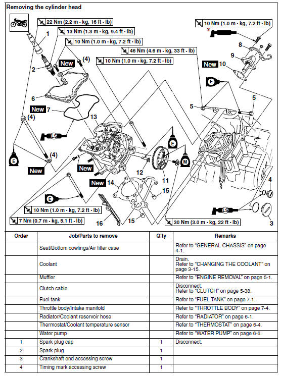
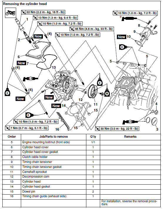
- Removing the cylinder head
- Checking the cylinder head
- Checking the camshaft sprocket and timing chain guide
- Checking the timing chain tensioner
- Checking the decompression system
- Installing the cylinder head
 Installing the exhaust assembly
1. Install:
Exhaust assembly "1"
Exhaust pipe nuts "2"
Exhaust assembly bolts "3" "4"
NOTE:
Do not fully tighten the nuts and bolts.
2. Tighten:
Exhaust pipe nuts "2"
Exhaust assem ...
 Removing the cylinder head
1. Align:
"I" mark "a" on the generator rotor
(with the stationary pointer "b" on the generator
cover)
a. Turn the crankshaft counterclockwise.
b. When the piston is at TDC on the compre ...
Other materials:
Checking the timing chain tensioner
1. Check:
Timing chain tensioner
Cracks/damage/rough movement Replace.
a. Lightly press the timing chain tensioner rod
into the timing chain tensioner housing by
hand.
NOTE:
While pressing the timing chain tensioner rod,
wind it clockwise with a thin screwdriver "1" until
it stops.
b. ...
Installing the relay arm
1. Lubricate:
Spacers
Bearings
Oil seals
Bolts (unthreaded shaft portion only)
2. Install:
Bearing "1"
(to the relay arm)
Oil seal "2"
(to the relay arm)
3. Rear shock absorber assembly
4. Relay arm
5. Connecting arm
A. Left side
B. Right side ...
General chassis
Installing the air filter case
1. Install:
Air filter case joint clamp
NOTE:
Align the projection "a" on the air filter case with
the slot "b" in the air filter case joint clamp.
...