Yamaha YZF-R125 Service Manual: Installing the cylinder head
1. Install:
- Cylinder head
NOTE:
Pass the timing chain through the timing chain cavity.
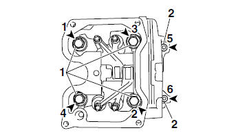
2. Tighten:
- Cylinder head bolts "1"
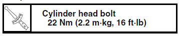
- Cylinder head bolts "2"
NOTE:
- Lubricate the cylinder head bolts and washers with engine oil.
- Tighten the cylinder head bolts in the proper tightening sequence as shown and torque them in two stages.
3. Install:
- Camshaft sprocket
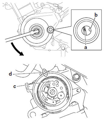
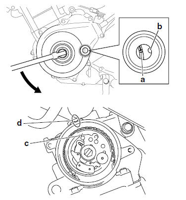
a. Turn the crankshaft counterclockwise.
b. Align the "I" mark "a" on the generator rotor with the stationary pointer "b" on the generator cover.
c. Align the "I" mark "c" on the camshaft sprocket with the stationary pointer "d" on the cylinder head.
d. Install the timing chain onto the camshaft sprocket, and then install the camshaft sprocket onto the camshaft.
NOTE:
When installing the camshaft sprocket, be sure to keep the timing chain as tight as possible on the exhaust side.
| CAUTION: Do not turn the crankshaft when installing the camshaft(s) to avoid damage or improper valve timing. |
e. While holding the camshaft, temporarily tighten the camshaft sprocket bolt.
f. Remove the wire from the timing chain.
4. Install:
- Timing chain tensioner gasket

- Timing chain tensioner
a. Apply sealant to the timing chain tensioner
bolt threads. 
b. While lightly pressing the timing chain tensioner rod by hand, turn the tensioner rod fully clockwise with a thin screwdriver "1".
c. With the timing chain tensioner rod turned all the way into the timing chain tensioner housing (with the thin screwdriver still installed), install the gasket and the timing chain tensioner "2" onto the cylinder block.
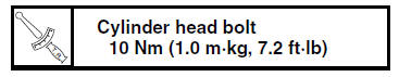
d. Tighten the timing chain tensioner bolts "3" to
the specified torque. 
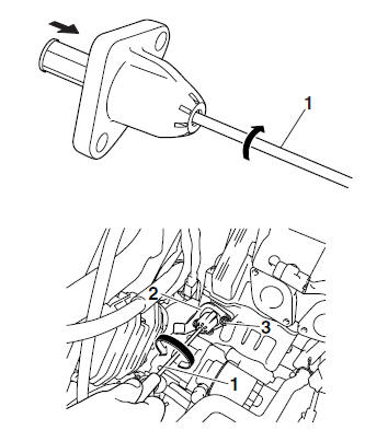
e. Remove the screwdriver, make sure the timing chain tensioner rod releases.
5. Turn:
- Crankshaft (several turns counterclockwise)
6. Check:
- "I" mark "a" Align the "I" mark on the generator rotor with the stationary pointer "b" on the generator cover.
- "I" mark "c"
Align the "I" mark on the camshaft sprocket
with the stationary pointer "d" on the cylinder
head.
Out of alignment
 Correct.
Refer to the installation steps above.
7. Tighten:
- Camshaft sprocket bolt
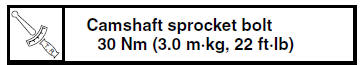
| CAUTION: Be sure to tighten the camshaft sprocket bolt to the specified torque to avoid the possibility of the bolt coming loose and damaging the engine. |
8. Measure:
Valve clearance
Out of specification  Adjust.
Refer to "ADJUSTING THE VALVE CLEARANCE" on page 3-3.
 Checking the decompression system
1. Check:
Decompression system
a. Check the decompression system with the
camshaft sprocket and the decompression
cam installed to the camshaft.
b. Check that the decompression lever "1"
...
 Camshaft
...
Other materials:
Checking the rear brake master cylinder
1. Check:
Brake master cylinder
Damage/scratches/wear Replace.
Brake fluid delivery passages
(brake master cylinder body)
Obstruction Blow out with
compressed air.
2. Check:
Brake master cylinder kit
Damage/scratches/wear Replace.
3. Check:
Brake fluid reservoir
Cracks/ ...
Adjusting the clutch lever free play
Adjusting the clutch lever free play
Clutch lever free play adjusting bolt
Clutch lever free play
The clutch lever free play should measure
10.0-15.0 mm (0.39-0.59 in) as
shown. Periodically check the clutch lever
free play and, if necessary, adjust it
as follows.
Slide the ...
Cable routing
Front brake light switch lead
Right handlebar switch lead
Throttle cable
Main switch
Clutch cable
Clutch switch lead
Left handlebar switch lead
Sub-wire harness
Horn
Speed sensor lead
Front brake hose
Main switch lead
Left headlight assembly lead
Right headlight asse ...