Yamaha YZF-R125 Service Manual: Intake air pressure sensor
1. Check:
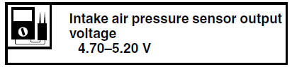
- Intake air pressure sensor output voltage
Out of specification Replace the throttle
body.
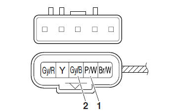
a. Connect the pocket tester (DC 20 V) to the
throttle body sensor assembly coupler as
shown.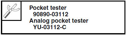
- Positive tester probe

pink/white "1" - Negative tester probe

gray/black "2"
b. Set the main switch to "ON".
c. Measure the intake air pressure sensor output voltage.
 Throttle position sensor
1. Check:
Throttle position sensor
a. Connect the digital circuit tester to the terminals
of the throttle body sensor assembly
coupler as shown.
Positive tester probe →
gray/red t ...
 Intake air temperature sensor
1. Check:
Intake air temperature sensor resistance
Out of specification Replace
the throttle
body.
a. Connect the pocket tester ( ×
1k) to the
throttle body sensor assembly co ...
Other materials:
Starting circuit cut-off system operation
If the engine stop switch is set to "
" and the main switch is set to
"ON" (both switches are closed), the
starter motor can only operate if at least one of the following conditions is
met:
The transmission is in neutral (the neutral switch is closed).
The clutch lever is pulled to the ...
Engine break-in
There is never a more important period
in the life of your engine than the period
between 0 and 1000 km (600 mi). For
this reason, you should read the following
material carefully.
Since the engine is brand new, do not
put an excessive load on it for the first
1000 km (600 mi). The vari ...
Front wheel
To remove the front wheel
WARNING
To avoid injury, securely support the
vehicle so there is no danger of it
falling over.
Loosen the front wheel axle pinch
bolt, then the wheel axle and the
brake caliper bolts.
Front wheel axle pinch bolt
Lift the front wheel of ...