Yamaha YZF-R125 Service Manual: Intake air temperature sensor
1. Check:
- Intake air temperature sensor resistance
Out of specification
 Replace
the throttle body.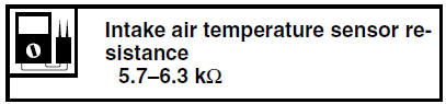
a. Connect the pocket tester (  ×
×
1k) to the
throttle body sensor assembly coupler as
shown.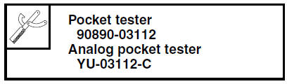
- Positive tester probe

brown/white "1" - Negative tester probe

gray/black "2"
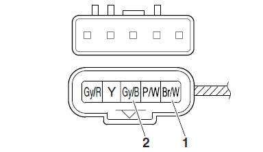
b. Measure the intake air temperature sensor resistance.
 Intake air pressure sensor
1. Check:
Intake air pressure sensor output voltage
Out of specification Replace the throttle
body.
a. Connect the pocket tester (DC 20 V) to the
throttle body sensor assembly coupler as
...
 Checking the fid (fast idle solenoid)
1. Disconnect:
FID (fast idle solenoid) coupler
2. Check:
FID (fast idle solenoid) resistance
a. Disconnect the FID (fast idle solenoid) coupler
from the FID.
b. Connect the pocket t ...
Other materials:
Incorrect engine idling speed
Engine
1. Cylinder and cylinder head
Incorrect valve clearance
Damaged valve train components
2. Air filter
Clogged air filter element
Fuel system
1. Throttle body
Damaged or loose throttle body joint
Improperly adjusted engine idling speed (idle
adjusting screw)
Improper ...
Avoid Carbon Monoxide Poisoning
All engine exhaust contains carbon
monoxide, a deadly gas. Breathing carbon
monoxide can cause headaches,
dizziness, drowsiness, nausea, confusion,
and eventually death.
Carbon Monoxide is a colorless, odorless,
tasteless gas which may be
present even if you do not see or smell
any en ...
Checking the fuel sender
1. Drain the fuel from the fuel tank.
2. Check:
Fuel sender resistance
Out of specification → Replace the fuel
sender.
a. Connect the pocket tester ( ×
10) to the fuel
sender coupler as shown.
Positive tester probe
sky blue "1"
Negative tester probe
orange/white " ...