Yamaha YZF-R125 Service Manual: Throttle position sensor
1. Check:
- Throttle position sensor
a. Connect the digital circuit tester to the terminals
of the throttle body sensor assembly
coupler as shown.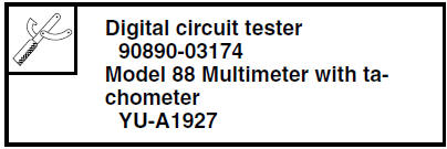
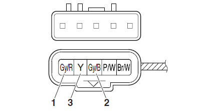
- Positive tester probe → gray/red terminal "1"
- Negative tester probe → gray/black terminal "2"
b. Measure the throttle position sensor input voltage.
Out of specification → Replace or repair the
wire harness.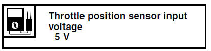
c. Connect the digital circuit tester to the terminals of the throttle body sensor assembly coupler as shown.
- Positive tester probe → yellow terminal "3"
- Negative tester probe → gray/black terminal "2"
d. While slowly opening the throttle, check that the throttle position sensor output voltage is increased.
Voltage does not change or it changes abruptly → Replace the throttle body.
Out of specification (closed position) →
Replace
the throttle body.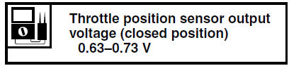
 Checking the throttle body sensor assembly
WARNING
Do not remove the throttle body sensor assembly.
Handle the throttle body sensor assembly
with special care
Never subject the throttle body sensor assembly
to strong ...
 Intake air pressure sensor
1. Check:
Intake air pressure sensor output voltage
Out of specification Replace the throttle
body.
a. Connect the pocket tester (DC 20 V) to the
throttle body sensor assembly coupler as
...
Other materials:
Cast wheels
To maximize the performance, durability,
and safe operation of your vehicle,
note the following points regarding the
specified wheels.
The wheel rims should be checked
for cracks, bends or warpage before
each ride. If any damage is
found, have a Yamaha dealer replace
the wheel. ...
Checking the camshaft
1. Check:
Camshaft lobes
Blue discoloration/pitting/scratches
Replace
the camshaft.
2. Measure:
Camshaft lobe dimensions "a" and "b"
Out of specification Replace
the camshaft.
3. Check:
Camshaft oil passage
Obstruction Blow out with
compressed air. ...
Checking the rear brake master cylinder
1. Check:
Brake master cylinder
Damage/scratches/wear Replace.
Brake fluid delivery passages
(brake master cylinder body)
Obstruction Blow out with
compressed air.
2. Check:
Brake master cylinder kit
Damage/scratches/wear Replace.
3. Check:
Brake fluid reservoir
Cracks/ ...