Yamaha YZF-R125 Service Manual: Balancer gear
- Removing the primary drive gear and balancer gears
- Checking the balancer gears and primary drive gear
- Installing the primary drive gear and balancer gears
 Installing the shift shaft
1. Install:
Stopper lever "1"
Stopper lever spring "2"
NOTE:
Install the stopper lever spring as shown in the
illustration.
Hook the ends of the stopper lever spring onto
the stoppe ...
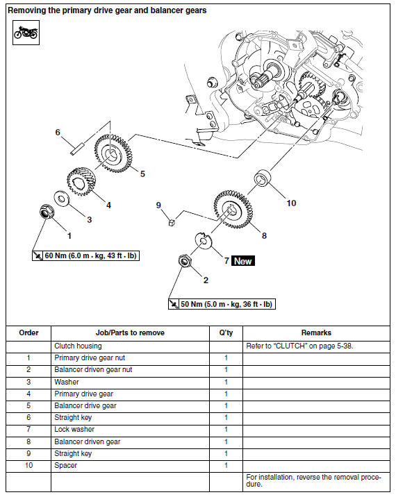
 Removing the primary drive gear and balancer gears
1. Loosen:
Primary drive gear nut "1"
NOTE:
Place the aluminum plate "a" between the balancer
drive gear "2" and the balancer driven
gear "3", and then loosen the primary drive gear
nut.
...
Other materials:
Lubricating the drive chain
The drive chain consists of many interacting
parts. If the drive chain is not maintained properly,
it will wear out quickly. Therefore, the drive
chain should be serviced, especially when the
vehicle is used in dusty areas.
This vehicle has a drive chain with small rubber
O-rings between eac ...
Checking the horn
1. Check:
Horn resistance
Out of specification Replace.
a. Disconnect the horn connectors from the
horn terminals.
b. Connect the pocket tester ( × 1) to the horn
terminals.
Positive tester probe
horn terminal "1"
Negative tester probe
horn terminal "2"
c. Measure t ...
Checking the rear shock absorber assembly
1. Check:
Rear shock absorber rod
Bends/damage Replace the rear
shock
absorber assembly.
Rear shock absorber
Oil leaks Replace the rear
shock absorber
assembly.
Spring
Damage/wear Replace the
rear shock absorber
assembly.
Bushing
Damage/wear Replace the rea ...