Yamaha YZF-R125 Service Manual: Installing the primary drive gear and balancer gears
1. Install:
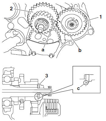
- Balancer driven gear "1"
- Lock washer

- Balancer drive gear "2"
- Primary drive gear
- Washer "3"
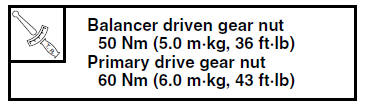
- Balancer driven gear nut
- Primary drive gear nut
NOTE:
- Align the punch mark "a" in the balancer drive gear "2" with the punch mark "b" in the balancer driven gear "1".
- Be sure to install the washer so that its sharp edge "c" is facing the primary drive gear.
2. Tighten:
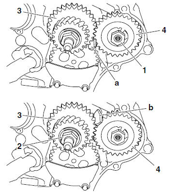
- Balancer driven gear nut "1"
- Primary drive gear nut "2"
NOTE:
- Place the aluminum plate "a" between the balancer drive gear "3" and the balancer driven gear "4", and then tighten the balancer driven gear nut.
- Place the aluminum plate "b" between the balancer drive gear "3" and the balancer driven gear "4", and then tighten the primary drive gear nut.
3. Bend the lock washer tab along a flat side of the nut.
 Checking the balancer gears and primary drive gear
1. Check:
Balancer drive gear
Balancer driven gear
Cracks/damage/wear Replace.
2. Check:
Primary drive gear
Refer to "CHECKING THE PRIMARY DRIVE
GEAR" on page 5-43.
...
 Crankcase
...
Other materials:
Checking the fid (fast idle solenoid)
1. Disconnect:
FID (fast idle solenoid) coupler
2. Check:
FID (fast idle solenoid) resistance
a. Disconnect the FID (fast idle solenoid) coupler
from the FID.
b. Connect the pocket tester ( × 10)
to the terminals
of the FID (fast idle solenoid).
Positive tester probe ...
Disassembling the water pump
1. Remove:
Water pump seal "1"
NOTE:
Remove the water pump seal from the inside of
the water pump housing "2".
2. Remove:
Bearing "1"
NOTE:
Remove the bearing from the outside of the water
pump housing "2".
...
Assembling the rear brake caliper
WARNING
Before installation, all internal brake components
should be cleaned and lubricated
with clean or new brake fluid.
Never use solvents on internal brake components
as they will cause the brake caliper
piston dust seal and piston seal to swell
and distort.
...