
Yamaha YZF-R125 Service Manual: Cleaning the air filter element
NOTE:
There is a check hose "1" at the bottom of the air filter case. If dust and/or water collects in this hose, clean the air filter element and air filter case.
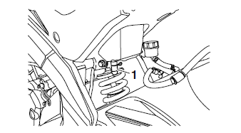
1. Remove:
- Rider seat Refer to "GENERAL CHASSIS" on page 4-1.
2. Remove:
- Fuel tank Refer to "FUEL TANK" on page 7-1.
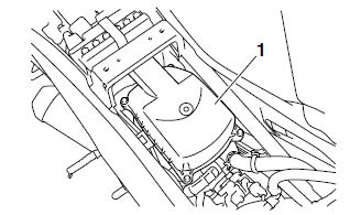
3. Remove:
- Air filter case cover "1"
- Air filter element
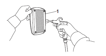
4. Clean:
- Air filter element "1" Apply compressed air to the outer surface of the air filter element.
5. Check:
- Air filter element
Damage
 Replace.
6. Install:
- Air filter element
- Air filter case cover (along with the gaskets)
| CAUTION: Never operate the engine without the air filter element installed. Unfiltered air will cause rapid wear of engine parts and may damage the engine. Operating the engine without the air filter element will also affect throttle body tuning, leading to poor engine performance and possible overheating. |
NOTE:
Make sure the air filter element is properly installed in the air filter case.
7. Install:
- Fuel tank Refer to "FUEL TANK" on page 7-1.
- Rider seat Refer to "GENERAL CHASSIS" on page 4-1.
 Adjusting the clutch cable free play
1. Check:
Clutch cable free play "a"
Out of specification Adjust.
2. Adjust:
Clutch cable free play
a. Pull back the rubber cover "1"
b. Loosen the locknut "2".
c. Turn the adjust ...
 Checking the throttle body joint and air filter case joint
1. Remove:
Right lower side cowling
Left lower side cowling
Refer to "GENERAL CHASSIS" on page 4-1.
2. Check:
Throttle body joint "1"
Air filter case joint "2"
Cracks/damage Replace ...
Other materials:
Checking the rear shock absorber assembly
1. Check:
Rear shock absorber rod
Bends/damage Replace the rear
shock
absorber assembly.
Rear shock absorber
Oil leaks Replace the rear
shock absorber
assembly.
Spring
Damage/wear Replace the
rear shock absorber
assembly.
Bushing
Damage/wear Replace the rea ...
Troubleshooting method
The engine operation is not normal and the
engine trouble warning light comes on.
1. Check:
Fault code number
a. Check the fault code number displayed on
the FI diagnostic tool.
b. Identify the faulty system with the fault code.
Refer to "Self-Diagnostic Function table".
c. Identi ...
Replacing the rear brake pads
NOTE:
When replacing the brake pads, it is not necessary
to disconnect the brake hose or disassemble
the brake caliper.
1. Remove:
Brake pads
Brake pad spring
NOTE:
To remove the inner brake pad "1", push down
on the brake caliper bracket so that there is
space to remove the brake pa ...