Yamaha YZF-R125 Service Manual: Starting circuit cut-off system operation
If the engine stop switch is set to "
 " and the main switch is set to
"ON" (both switches are closed), the
starter motor can only operate if at least one of the following conditions is
met:
- The transmission is in neutral (the neutral switch is closed).
- The clutch lever is pulled to the handlebar (the clutch switch is closed) and the sidestand is up (the sidestand switch is closed).
The starting circuit cut-off relay prevents the starter motor from operating
when neither of these conditions
has been met. In this instance, the starting circuit cut-off relay is open so
current cannot reach the
starter motor. When at least one of the above conditions has been met, the
starting circuit cut-off relay
is closed and the engine can be started by pressing the start switch "
".
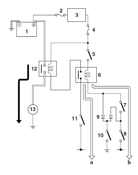
a. WHEN THE TRANSMISSION IS IN NEUTRAL
b. WHEN CLUTCH LEVER IS PULLED TO THE HANDLEBAR AND THE SIDESTAND IS UP
1. Battery
2. Main fuse
3. Main switch
4. Ignition fuse
5. Engine stop switch
6. Starting circuit cut-off relay
7. Clutch switch
8. Sidestand switch
9. Diode
10.Neutral switch
11.Start switch
12.Starter relay
13.Starter motor
 Circuit diagram
4. Main fuse
5. Main switch
7. Clutch switch
8. Sidestand switch
9. Battery
10.Starter relay
11.Starter motor
12.Starting circuit cut-off relay
13.Diode
14.Neutral switch
16.Start switch ...
 Troubleshooting
The starter motor fails to turn.
NOTE:
Before troubleshooting, remove the following part(s):
1. Seats
2. Fuel tank
3. Left lower side cowling
4. Left upper side cowling
...
Other materials:
Troubleshooting details
This section describes the measures per fault code number displayed on the FI
diagnostic tool. Check
and service the items or components that are the probable cause of the
malfunction following the order
given.
After the check and service of the malfunctioning part have been completed,
re ...
Checking the starter motor operation
1. Check:
Starter motor operation
Does not operate → Perform the electric
starting system troubleshooting, starting with
step 4.
Refer to "TROUBLESHOOTING" on page
8-9.
a. Connect the positive battery terminal "1" and
starter motor lead "2" with a jumper lead "3".
W ...
Checking the bulbs and bulb sockets
NOTE:
Do not check any of the lights that use LEDs.
Check each bulb and bulb socket for damage or
wear, proper connections, and also for continuity
between the terminals.
Damage/wear Repair or replace
the bulb,
bulb socket or both.
Improperly connected Properly
connect.
No c ...