Yamaha YZF-R125 Service Manual: Circuit diagram
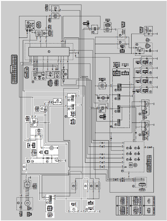
4. Main fuse
5. Main switch
7. Clutch switch
8. Sidestand switch
9. Battery
10.Starter relay
11.Starter motor
12.Starting circuit cut-off relay
13.Diode
14.Neutral switch
16.Start switch
17.Engine stop switch
64.Ignition fuse

 Starting circuit cut-off system operation
If the engine stop switch is set to "
" and the main switch is set to
"ON" (both switches are closed), the
starter motor can only operate if at least one of the following conditions is
met:
...
Other materials:
Checking the valve seats
The following procedure applies to all of the
valves and valve seats.
1. Eliminate:
Carbon deposits
(from the valve face and valve seat)
2. Check:
Valve seat
Pitting/wear Replace the
cylinder head.
3. Measure:
Valve seat width C "a"
Out of specification Replace
the ...
Removing the crankshaft
1. Remove:
Crankshaft "1"
NOTE:
Remove the crankshaft with the crankcase
separating tool "2".
Make sure the crankcase separating tool is
centered over the crankshaft.
CAUTION:
To protect the end of the crankshaft, place
an appropriate sized socket between the
c ...
Checking and lubricating the brake and clutch levers
Brake lever
Brake lever
Clutch lever
Clutch lever
The operation of the brake and clutch
levers should be checked before each
ride, and the lever pivots should be lubricated
if necessary.
Recommended lubricants:Brake lever:
Silicone grease
Clutch lever:
Lithium-soap ...