Yamaha YZF-R125 Service Manual: Fi system
The fuel pump delivers fuel to the fuel injector via the fuel filter. The pressure regulator maintains the fuel pressure that is applied to the fuel injector at only 250 kPa (2.50 kg/cm², 36.3 psi). Accordingly, when the energizing signal from the ECU energizes the fuel injector, the fuel passage opens, causing the fuel to be injected into the intake manifold only during the time the passage remains open. Therefore, the longer the length of time the fuel injector is energized (injection duration), the greater the volume of fuel that is supplied. Conversely, the shorter the length of time the fuel injector is energized (injection duration), the lesser the volume of fuel that is supplied.
The injection duration and the injection timing are controlled by the ECU. Signals that are input from the throttle position sensor, crankshaft position sensor, intake air pressure sensor, intake air temperature sensor, lean angle sensor and coolant temperature sensor enable the ECU to determine the injection duration. The injection timing is determined through the signals from the crankshaft position sensor. As a result, the volume of fuel that is required by the engine can be supplied at all times in accordance with the driving conditions.
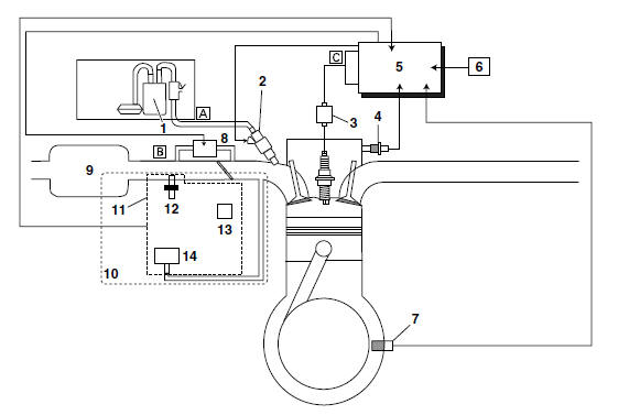
- Fuel pump
- Fuel injector
- Ignition coil
- Coolant temperature sensor
- ECU (engine control unit)
- Lean angle sensor
- Crankshaft position sensor
- FID (fast idle solenoid)
- Air filter case
- Throttle body
- Throttle body sensor assembly
- Intake air temperature sensor
- Throttle position sensor
- Intake air pressure sensor
- Fuel system
- Air system
- Control system
 Outline of the fi system
The main function of a fuel supply system is to provide fuel to the
combustion chamber at the optimum
air-fuel ratio in accordance with the engine operating conditions and the
atmospheric tempera ...
 Multi-function display
1. Multi-function display
2. "RESET/SELECT" button
The multi-function display is equipped with the
following:
a speedometer (which shows the riding speed)
an odometer (which shows the t ...
Other materials:
Troubleshooting method
The engine operation is not normal and the
engine trouble warning light comes on.
1. Check:
Fault code number
a. Check the fault code number displayed on
the FI diagnostic tool.
b. Identify the faulty system with the fault code.
Refer to "Self-Diagnostic Function table".
c. Identi ...
Checking the fuel sender
1. Drain the fuel from the fuel tank.
2. Check:
Fuel sender resistance
Out of specification → Replace the fuel
sender.
a. Connect the pocket tester ( ×
10) to the fuel
sender coupler as shown.
Positive tester probe
sky blue "1"
Negative tester probe
orange/white " ...
Important manual information
Particularly important information is distinguished in this manual by the
following notations:
This is the safety alert symbol. It is used to alert you to potential personal
injury
hazards. Obey all safety messages that follow this symbol to avoid possible
injury
or death.
WARNING
...