Yamaha YZF-R125 Service Manual: Checking the turn signal relay
1. Check:
Turn signal relay input voltage
Out of specification →The wiring circuit
from
the main switch to the turn signal relay coupler
is faulty and must be repaired.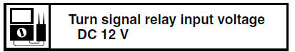
a. Connect the pocket tester (DC 20 V) to the
turn signal relay terminal as shown.
- Positive tester probe 
brown "1"
- Negative tester probe 
ground 
b. Set the main switch to "ON".
c. Measure the turn signal relay input voltage.
2. Check:
Turn signal relay output voltage
Out of specification Replace.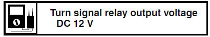
a. Connect the pocket tester (DC 20 V) to the
turn signal relay terminal as shown. 
Positive tester probe
brown/white "1"
Negative tester probe
ground
b. Set the main switch to "ON".
c. Measure the turn signal relay output voltage.
 Checking the relays
Check each switch for continuity with the pocket
tester. If the continuity reading is incorrect, replace
the relay.
1. Disconnect the relay from the wire harness.
2. Connect the pocket tester ( ...
 Checking the diode
1. Check:
Diode
Out of specification Replace.
NOTE:
The pocket tester or the analog pocket tester
readings are shown in the following table.
a. Disconnect the diode from the wire harness.
...
Other materials:
Installing the shift shaft
1. Install:
Stopper lever "1"
Stopper lever spring "2"
NOTE:
Install the stopper lever spring as shown in the
illustration.
Hook the ends of the stopper lever spring onto
the stopper lever and the crankcase boss "3".
Mesh the stopper lever with the shift drum segment
assembly. ...
Rider seat
To remove the rider seat
Insert the key into the seat lock,
and then turn it clockwise.
Seat lock
Open.
Pull the rider seat off.
To install the rider seat
1. Insert the projection on the front of
the rider seat into the seat holder
as shown.
Projection
...
Checking the stator coil
1. Disconnect:
Stator coil coupler
(from the wire harness)
2. Check:
Stator coil resistance
Out of specification → Replace the
crankshaft
position sensor/stator assembly.
a. Connect the pocket tester ( ×
1) to the stator
coil coupler as shown.
b. Measure the sta ...