Yamaha YZF-R125 Service Manual: Checking the relays
Check each switch for continuity with the pocket
tester. If the continuity reading is incorrect, replace
the relay. 
1. Disconnect the relay from the wire harness.
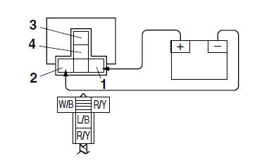
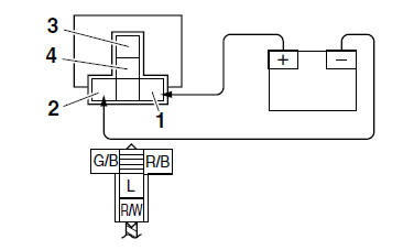
2. Connect the pocket tester ( × 1) and battery (12 V) to the relay terminal as shown.
Check the relay operation.
Out of specification → Replace.
Starter relay
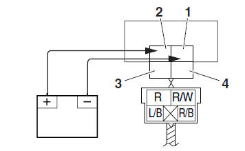
1. Positive battery terminal
2. Negative battery terminal
3. Positive tester probe
4. Negative tester probe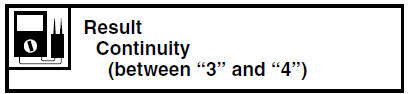
Starting circuit cut-off relay
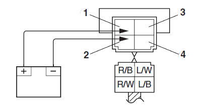
1. Positive battery terminal
2. Negative battery terminal
3. Positive tester probe
4. Negative tester probe 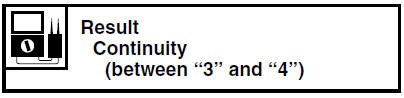
Headlight relay
1. Positive battery terminal
2. Negative battery terminal
3. Positive tester probe
4. Negative tester probe 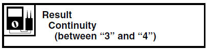
Radiator fan motor relay
1. Positive battery terminal
2. Negative battery terminal
3. Positive tester probe
4. Negative tester probe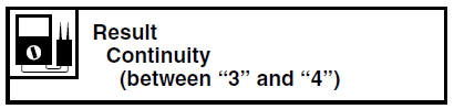
 Checking and charging the battery
WARNINGBatteries generate explosive hydrogen gas
and contain electrolyte which is made of poisonous
and highly caustic sulfuric acid.
Therefore, always follow these preventive
mea ...
 Checking the turn signal relay
1. Check:
Turn signal relay input voltage
Out of specification →The wiring circuit
from
the main switch to the turn signal relay coupler
is faulty and must be repaired.
a. Connect the poc ...
Other materials:
Clutch lever
Clutch lever
Clutch lever
The clutch lever is located at the left
handlebar grip. To disengage the
clutch, pull the lever toward the handlebar
grip. To engage the clutch, release
the lever. The lever should be pulled
rapidly and released slowly for smooth
clutch operation.
Th ...
General information
NOTICEThis manual was produced by MBK Industrie.
primarily for use by Yamaha dealers and their qualified
mechanics. It is not possible to include all the knowledge of a mechanic
in one manual. Therefore, anyone
who uses this book to perform maintenance and repairs on Yamaha vehi ...
Removing the generator
1. Remove:
Generator rotor nut "1"
Washer
NOTE:
While holding the generator rotor "2" with the
sheave holder "3", loosen the generator rotor
nut.
Do not allow the sheave holder to touch the
projection on the generator rotor.
2. Remove:
Generator rotor "1"
(with the ...