Yamaha YZF-R125 Service Manual: Checking the coolant level
1. Stand the vehicle on a level surface.
NOTE:
- Place the vehicle on a suitable stand.
- Make sure the vehicle is upright.
2. Check:
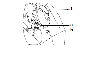
Coolant level The coolant level should be between the maximum level mark "a" and minimum level mark "b".
Below the minimum level mark → Add the recommended coolant to the proper level.
NOTE:
To access the coolant reservoir cap "1", remove the right side cover. Refer to "GENERAL CHASSIS" on page 4-1.
CAUTION:
|
3. Start the engine, warm it up for several minutes, and then turn it off.
4. Check:
- Coolant level
NOTE:
Before checking the coolant level, wait a few minutes until it settles.
 Checking the exhaust system
1. Check:
Exhaust assembly "1"
Cracks/damage → Replace.
Exhaust pipe gasket "2"
Exhaust gas leaks → Replace.
2. Check:
Tightening torques of the exhaust pipe nuts
"3" an ...
 Checking the cooling system
1. Remove:
Side covers
Upper side cowlings
Refer to "GENERAL CHASSIS" on page 4-1.
2. Check:
Radiator "1"
Radiator inlet hose "2"
Radiator outlet hose "3"
Coolant reservoir hose ...
Other materials:
Checking the condition of the bulb sockets
The following procedure applies to all of the bulb
sockets.
1. Check:
Bulb socket (for continuity)
(with the pocket tester)
No continuity Replace.
NOTE:
Check each bulb socket for continuity in the
same manner as described in the bulb section,
however, note the following.
a. Install a ...
Safe Riding
Perform the pre-operation checks each
time you use the vehicle to make sure it
is in safe operating condition. Failure to
inspect or maintain the vehicle properly
increases the possibility of an accident
or equipment damage. See page 4-1
for a list of pre-operation checks.
This motor ...
Multi-function display
1. Multi-function display
2. "RESET/SELECT" button
The multi-function display is equipped with the
following:
a speedometer (which shows the riding speed)
an odometer (which shows the total distance
traveled)
two tripmeters (which show the distance traveled
since they were last ...