Yamaha YZF-R125 Service Manual: Checking the valves and valve guides
The following procedure applies to all of the valves and valve guides.
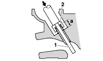
1. Measure:
- Valve-stem-to-valve-guide clearance
Out of specification
 Replace the
valve guide.
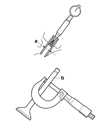
Valve-stem-to-valve-guide clearance =
Valve guide inside diameter "a" -
Valve stem diameter "b" 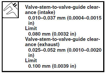
2. Replace:
- Valve guide
NOTE:
To ease valve guide removal and installation, and to maintain the correct fit, heat the cylinder head to 100 C (212 F) in an oven.
a. Remove the valve guide with the valve guide remover "1".
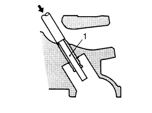
b. Install the new valve guide with the valve
guide installer "2" and valve guide remover
"1". 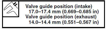
a. Valve guide position
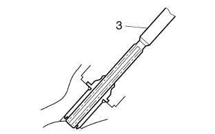
c. After installing the valve guide, bore the valve guide with the valve guide reamer "3" to obtain the proper valve-stem-to-valve-guide clearance.
NOTE:
After replacing the valve guide, reface the valve
seat. 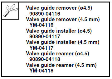
3. Eliminate:
- Carbon deposits (from the valve face and valve seat)
4. Check:
- Valve face
Pitting/wear
 Grind the valve
face. - Valve stem end
Mushroom shape or diameter larger than the
body of the valve stem
 Replace
the valve.
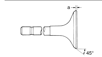
5. Measure:
- Valve margin thickness D "a"
Out of specification Replace
the valve.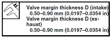
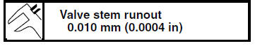
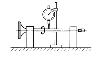
6. Measure:
- Valve stem runout
Out of specification Replace
the valve.
NOTE:
- When installing a new valve, always replace the valve guide.
- If the valve is removed or replaced, always replace
the valve stem seal.
 Removing the valves
The following procedure applies to all of the
valves and related components.
NOTE:
Before removing the internal parts of the cylinder
head (e.g., valves, valve springs, valve seats),
make sure th ...
 Checking the valve seats
The following procedure applies to all of the
valves and valve seats.
1. Eliminate:
Carbon deposits
(from the valve face and valve seat)
2. Check:
Valve seat
Pitting/wear Replace the ...
Other materials:
Checking the switches
1. Clutch switch
2. Main switch
3. Front brake light switch
4. Sidestand switch
5. Rear brake light switch
6. Neutral switch
7. Turn signal switch
8. Horn switch
9. Dimmer switch
10.Pass switch
11.Engine stop switch
12.Start switch
Check each switch for continuity with the pocket tes ...
Checking the fuses
The following procedure applies to all of the fuses.
CAUTION:To avoid a short circuit, always turn the
main
switch to "OFF" when checking or replacing
a fuse.
1. Remove:
Rider seat
Refer to "GENERAL CHASSIS" on page 4-1.
2. Check:
Fuse
a. Connect the pocket te ...
Checking the coolant level
1. Stand the vehicle on a level surface.
NOTE:
Place the vehicle on a suitable stand.
Make sure the vehicle is upright.
2. Check:
Coolant level
The coolant level should be between the
maximum level mark "a" and minimum level
mark "b".
Below the minimum level mark → Add t ...