
Yamaha YZF-R125 Service Manual: Checking the brake fluid level
1. Stand the vehicle on a level surface.
NOTE:
- Place the vehicle on a suitable stand.
- Make sure the vehicle is upright.
2. Check:
Brake fluid level
Below the minimum level mark "a" → Add the
recommended brake fluid to the proper level.
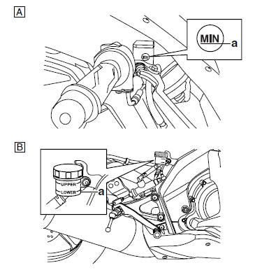
A. Front brake
B. Rear brake
WARNING
|
| CAUTION: Brake fluid may damage painted surfaces and plastic parts. Therefore, always clean up any spilt brake fluid immediately. |
NOTE:
In order to ensure a correct reading of the brake fluid level, make sure the top of the brake fluid reservoir is horizontal.
 Adjusting the rear disc brake
1. Check:
Brake pedal position
(distance "a" from the center of the rider footrest
to the center of the brake pedal)
Out of specification Adjust.
2. Adjust:
Brake pedal position
...
 Checking the front brake pads
The following procedure applies to all of the
brake pads.
1. Operate the brake.
2. Check:
Front brake pad
Wear indicator grooves "a" have almost disappeared
Replace the brake pads as a ...
Other materials:
Installing the clutch
1. Install:
Conical spring washer "1"
NOTE:
Install the conical spring washer as shown in the
illustration.
2. Install:
Clutch housing
Thrust washer "1"
NOTE:
Be sure to install the thrust washer so that its
sharp edge "a" is facing away from the clutch
boss.
3. Instal ...
Setting the normal mode
NOTE:
The engine speed, coolant temperature, and fault code, if detected, can be
displayed on the LCD of the
FI diagnostic tool when the tool is connected to the vehicle and is set to the
normal mode.
1. Set the main switch to "OFF" and the engine stop switch to "".
2. Disconnect the self- ...
Circuit diagram
4. Main fuse
5. Main switch
9. Battery
14.Neutral switch
25.ECU (engine control unit)
31.Fuel sender
34.Rear brake light switch
35.Front brake light switch
37.Tail/brake light
38.Rear right turn signal light
39.Rear left turn signal light
40.Front right turn signal light
41.Front lef ...