
Yamaha YZF-R125 Service Manual: Adjusting the exhaust gas volume
NOTE:
Be sure to set the CO density level to standard, and then adjust the exhaust gas volume.
1. Remove:
- Rider seat Refer to "GENERAL CHASSIS" on page 4-1.
2. Set the main switch to "OFF".
3. Disconnect:
- Self-diagnosis signal connector "1"
4. Connect:
- FI diagnostic tool "2"

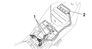
5. While pressing the "MODE" button "1", turn the main switch to "ON".
NOTE:
- "DIAG" appears on the LCD "2" of the FI diagnostic tool.
- "POWER" LED (Green) "3" comes on.
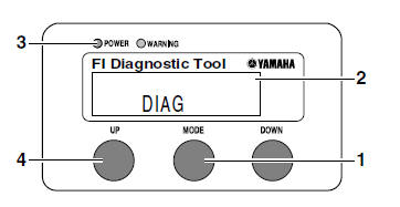
6. Press the "UP" button "4" to select the CO adjustment mode "CO" or the diagnostic mode "DIAG".
7. After selecting "CO", press the "MODE" button.
8. Check that "C1" appears on the LCD of the FI diagnostic tool, and then press the "MODE" button.
9. Start the engine.
| CAUTION: Perform the adjustment after the battery has been sufficiently charged. |
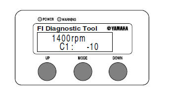
10.Change the CO adjustment volume by pressing the "UP" and "DOWN" buttons.
NOTE:
The CO adjustment volume and engine idling speed appears on the LCD of the FI diagnostic tool.
- To decrease the CO adjustment volume, press the "DOWN" button.
- To increase the CO adjustment volume, press the "UP" button.
11.Release the "DOWN" and "UP" buttons to execute the selection.
12.Set the main switch to "OFF" to cancel the mode.
13.Disconnect:
- FI diagnostic tool
14.Connect:
- Self-diagnosis signal connector
15.Install:
- Rider seat Refer to "GENERAL CHASSIS" on page 4-1.
 Adjusting the valve clearance
The following procedure applies to all of the
valves.
NOTE:
Valve clearance adjustment should be made
on a cold engine, at room temperature.
When the valve clearance is to be measured or
a ...
 Adjusting the engine idling speed
NOTE:
Prior to adjusting the engine idling speed, the air
filter element should be clean, and the engine
should have adequate compression.
1. Start the engine and let it warm up for several
minut ...
Other materials:
Checking the coolant level
1. Stand the vehicle on a level surface.
NOTE:
Place the vehicle on a suitable stand.
Make sure the vehicle is upright.
2. Check:
Coolant level
The coolant level should be between the
maximum level mark "a" and minimum level
mark "b".
Below the minimum level mark → Add t ...
Checking and lubricating the sidestand
Checking and lubricating the sidestand
The operation of the sidestand should
be checked before each ride, and the
sidestand pivot and metal-to-metal
contact surfaces should be lubricated if
necessary.
WARNING
If the sidestand does not move up
and down smoothly, have a Yamaha
deal ...
Circuit diagram
2. Crankshaft position sensor
4. Main fuse
5. Main switch
6. Radiator fan motor fuse
8. Sidestand switch
9. Battery
17.Engine stop switch
19.Intake air pressure sensor
20.Intake air temperature sensor
21.Throttle position sensor
22.Coolant temperature sensor
23.Lean angle sensor
24.S ...