Yamaha YZF-R125 Service Manual: Checking and adjusting the steering head
1. Stand the vehicle on a level surface
| WARNING Securely support the vehicle so that there is no danger of it falling over. |
NOTE:
Place the vehicle on a suitable stand so that the front wheel is elevated.
2. Check:
- Steering head
Grasp the bottom of the front fork legs and
gently rock the front fork.
Binding/looseness → Adjust the steering head.
3. Remove:
- Upper bracket Refer to "STEERING HEAD" on page 4-52.
4. Adjust:
- Steering head
a. Remove the lock washer "1", the upper ring nut "2", and the rubber washer "3".
b. Tighten the lower ring nut "4" with a steering nut wrench "5".
NOTE:
Set the torque wrench at a right angle to the steering nut wrench.
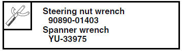
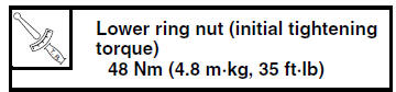
c. Loosen the lower ring nut "4" completely, and then tighten it to specification with a steering nut wrench.
| WARNING Do not overtighten the lower ring nut. |
d. Check the steering head for looseness or binding by turning the front fork all the way in both directions. If any binding is felt, remove the lower bracket and check the upper and lower bearings.
Refer to "STEERING HEAD" on page 4-52.
e. Install the rubber washer "3".
f. Install the upper ring nut "2".
g. Finger tighten the upper ring nut "2", and then align the slots of both ring nuts. If necessary, hold the lower ring nut and tighten the upper ring nut until their slots are aligned.
NOTE:
Make sure the lock washer tabs "a" sit correctly in the ring nut slots "b".
5. Install:
- Upper bracket Refer to "STEERING HEAD" on page 4-52.
 Lubricating the drive chain
The drive chain consists of many interacting
parts. If the drive chain is not maintained properly,
it will wear out quickly. Therefore, the drive
chain should be serviced, especially when the
vehi ...
 Checking the front fork
1. Stand the vehicle on a level surface.
WARNINGSecurely support the vehicle so that there
is
no danger of it falling over.
2. Check:
Inner tube
Damage/scratches Replace.
...
Other materials:
Removing the rear brake caliper
NOTE:
Before disassembling the brake caliper, drain
the brake fluid from the entire brake system.
1. Remove:
Union bolt "1"
Copper washers "2"
Brake hose "3"
NOTE:
Put the end of the brake hose into a container
and pump out the brake fluid carefully. ...
Checking the radiator
1. Check:
Radiator fins
obstruction clean.
Apply compressed air to the rear of the radiator.
Damage repair or replace.
NOTE:
Straighten any flattened fins with a thin, flat-head
screwdriver.
2. Check:
Radiator hoses
Cracks/damage Replace.
3. Measure:
Radiator cap ...
Intake air pressure sensor
1. Check:
Intake air pressure sensor output voltage
Out of specification Replace the throttle
body.
a. Connect the pocket tester (DC 20 V) to the
throttle body sensor assembly coupler as
shown.
Positive tester probe
pink/white "1"
Negative tester probe
gray/black "2"
...