Yamaha YZF-R125 Service Manual: Cylinder head
* Yamaha bond No. 1215 (Three Bond No. 1215)
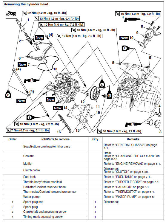
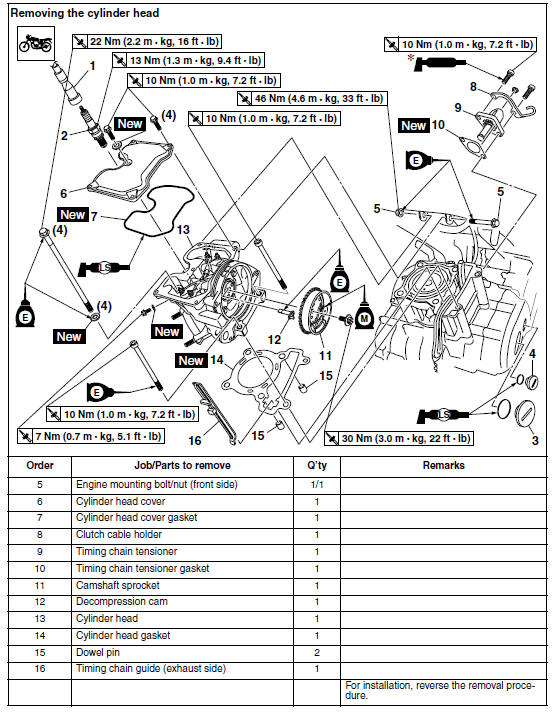
- Removing the cylinder head
- Checking the cylinder head
- Checking the camshaft sprocket and timing chain guide
- Checking the timing chain tensioner
- Checking the decompression system
- Installing the cylinder head
 Installing the exhaust assembly
1. Install:
Exhaust assembly "1"
Exhaust pipe nuts "2"
Exhaust assembly bolts "3" "4"
NOTE:
Do not fully tighten the nuts and bolts.
2. Tighten:
Exhaust pipe nuts "2"
Exhaust assem ...
 Removing the cylinder head
1. Align:
"I" mark "a" on the generator rotor
(with the stationary pointer "b" on the generator
cover)
a. Turn the crankshaft counterclockwise.
b. When the piston is at TDC on the compre ...
Other materials:
Removing the crankshaft
1. Remove:
Crankshaft "1"
NOTE:
Remove the crankshaft with the crankcase
separating tool "2".
Make sure the crankcase separating tool is
centered over the crankshaft.
CAUTION:
To protect the end of the crankshaft, place
an appropriate sized socket between the
c ...
Operation and important riding points
Read the Owner's Manual carefully to
become familiar with all controls. If
there is a control or function you do not
understand, ask your Yamaha dealer.
WARNING
Failure to familiarize yourself with
the controls can lead to loss of control,
which could cause an accident
or injury.
TIP ...
Troubleshooting
Although Yamaha motorcycles receive
a thorough inspection before shipment
from the factory, trouble may occur during
operation. Any problem in the fuel,
compression, or ignition systems, for
example, can cause poor starting and
loss of power.
The following troubleshooting charts
repre ...