Yamaha YZF-R125 Service Manual: Installing the cylinder head
1. Install:
- Cylinder head
NOTE:
Pass the timing chain through the timing chain cavity.
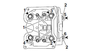
2. Tighten:
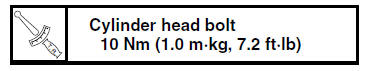
- Cylinder head bolts "1"
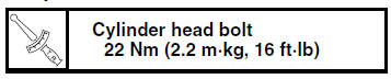
- Cylinder head bolts "2"
NOTE:
- Lubricate the cylinder head bolts and washers with engine oil.
- Tighten the cylinder head bolts in the proper tightening sequence as shown and torque them in two stages.
3. Install:
- Camshaft sprocket
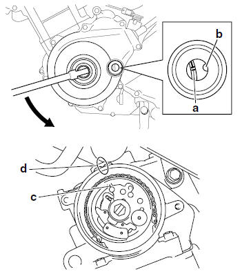
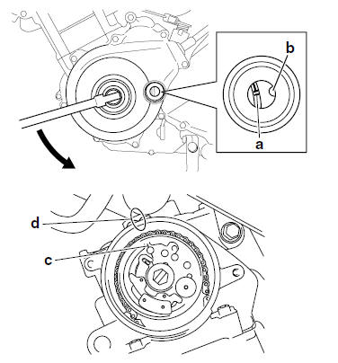
a. Turn the crankshaft counterclockwise.
b. Align the "I" mark "a" on the generator rotor with the stationary pointer "b" on the generator cover.
c. Align the "I" mark "c" on the camshaft sprocket with the stationary pointer "d" on the cylinder head.
d. Install the timing chain onto the camshaft sprocket, and then install the camshaft sprocket onto the camshaft.
NOTE:
When installing the camshaft sprocket, be sure to keep the timing chain as tight as possible on the exhaust side.
| CAUTION: Do not turn the crankshaft when installing the camshaft(s) to avoid damage or improper valve timing. |
e. While holding the camshaft, temporarily tighten the camshaft sprocket bolt.
f. Remove the wire from the timing chain.
4. Install:
- Timing chain tensioner gasket

- Timing chain tensioner
a. Apply sealant to the timing chain tensioner
bolt threads. 
b. While lightly pressing the timing chain tensioner rod by hand, turn the tensioner rod fully clockwise with a thin screwdriver "1".
c. With the timing chain tensioner rod turned all the way into the timing chain tensioner housing (with the thin screwdriver still installed), install the gasket and the timing chain tensioner "2" onto the cylinder block.
d. Tighten the timing chain tensioner bolts "3" to
the specified torque. 
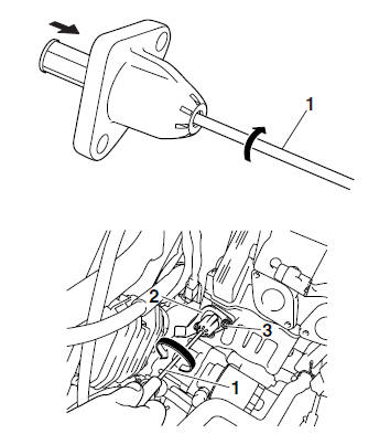
e. Remove the screwdriver, make sure the timing chain tensioner rod releases.
5. Turn:
- Crankshaft (several turns counterclockwise)
6. Check:
- "I" mark "a" Align the "I" mark on the generator rotor with the stationary pointer "b" on the generator cover.
- "I" mark "c"
Align the "I" mark on the camshaft sprocket
with the stationary pointer "d" on the cylinder
head.
Out of alignment
 Correct.
Refer to the installation steps above.
7. Tighten:
- Camshaft sprocket bolt
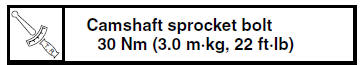
| CAUTION: Be sure to tighten the camshaft sprocket bolt to the specified torque to avoid the possibility of the bolt coming loose and damaging the engine. |
8. Measure:
Valve clearance
Out of specification  Adjust.
Refer to "ADJUSTING THE VALVE CLEARANCE" on page 3-3.
 Checking the decompression system
1. Check:
Decompression system
a. Check the decompression system with the
camshaft sprocket and the decompression
cam installed to the camshaft.
b. Check that the decompression lever "1"
...
 Camshaft
...
Other materials:
Bleeding the hydraulic brake system
WARNINGBleed the hydraulic brake system whenever:
the system is disassembled.
a brake hose is loosened, disconnected or
replaced.
the brake fluid level is very low.
brake operation is faulty.
NOTE:
Be careful not to spill any brake fluid or allow
th ...
Overheating
Engine
1. Clogged coolant passages
Cylinder head and piston
Heavy carbon buildup
2. Engine oil
Incorrect oil level
Incorrect oil viscosity
Inferior oil quality
Cooling system
1. Coolant
Low coolant level
2. Radiator
Damaged or leaking radiator
Faulty radiator cap
...
Checking the decompression system
1. Check:
Decompression system
a. Check the decompression system with the
camshaft sprocket and the decompression
cam installed to the camshaft.
b. Check that the decompression lever "1"
moves smoothly.
c. Without operating the decompression lever,
check that the decompression cam " ...