Yamaha YZF-R125 Service Manual: Troubleshooting details
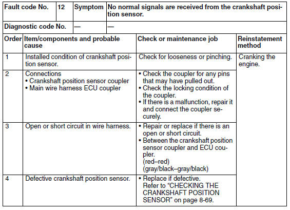
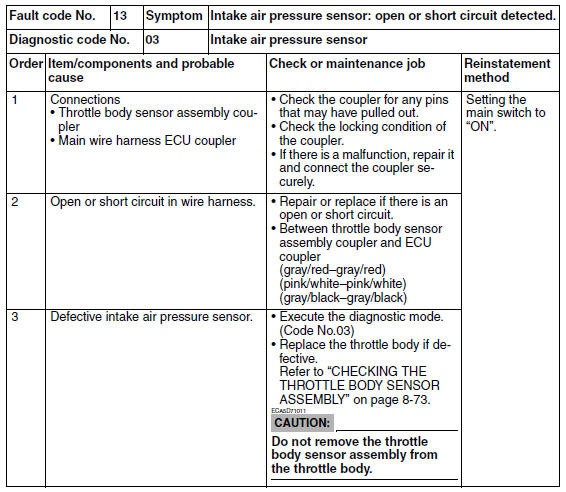
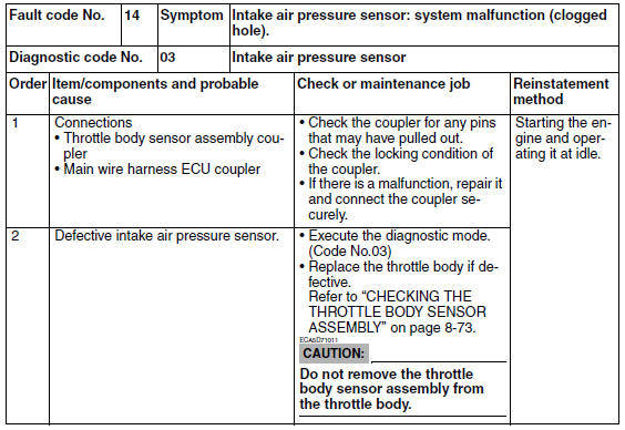
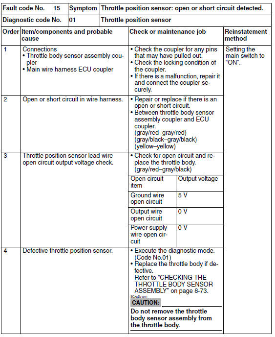
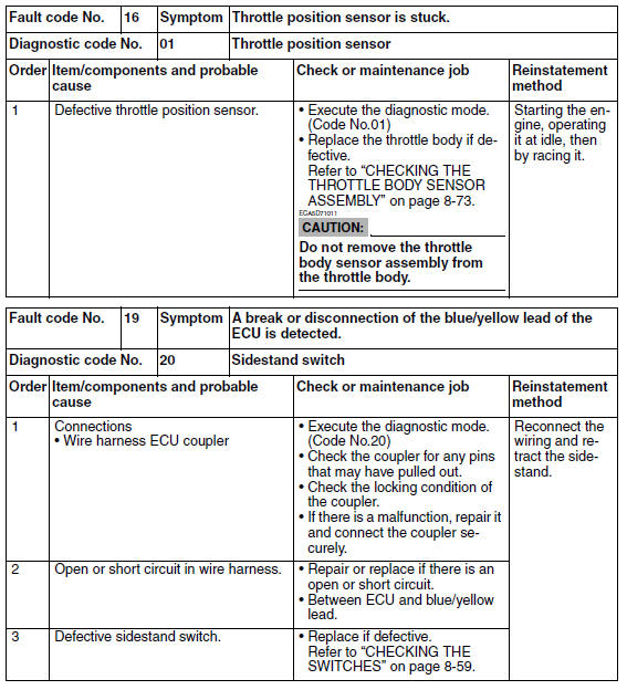
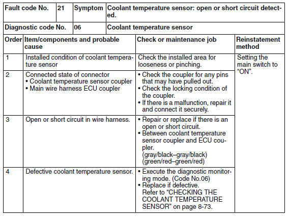
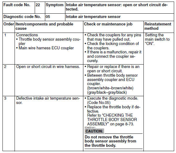
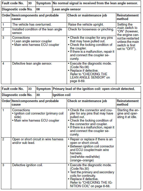
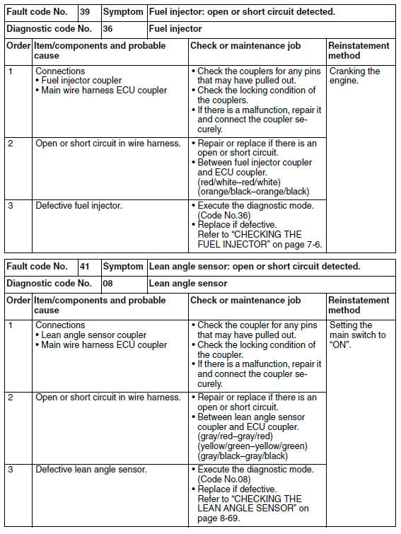
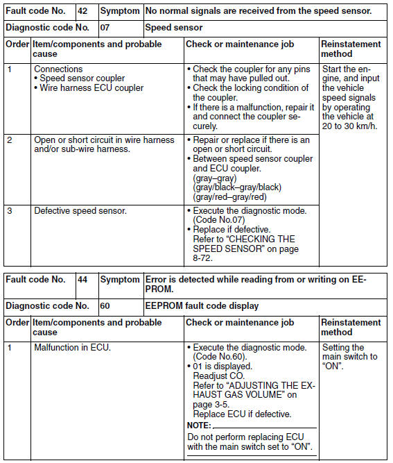
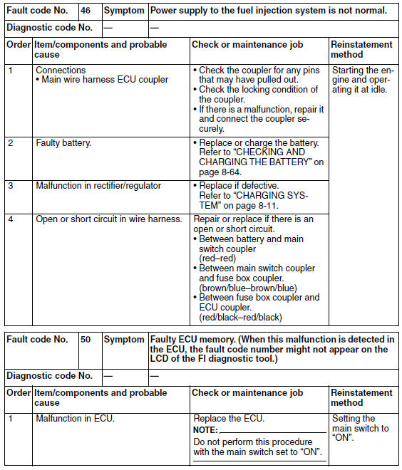
This section describes the measures per fault code number displayed on the FI diagnostic tool. Check and service the items or components that are the probable cause of the malfunction following the order given.
After the check and service of the malfunctioning part have been completed, reset the FI diagnostic tool display according to the reinstatement method.
Fault code No.: Fault code number displayed on the FI diagnostic tool when the engine failed to work normally. Refer to "Diagnostic code table".
Diagnostic code No.: Diagnostic code number to be used when the diagnostic mode is operated. Refer to "Sensor operation table" and "Actuator operation table".
 Setting the diagnostic mode
1. Set the main switch to "OFF" and the engine stop switch to "
".
2. Disconnect the self-diagnosis signal connector "1", and then connect the FI
diagnostic tool "2" as
shown.
3. Disconnect ...
 Fuel pump system
...
Other materials:
Checking the cylinder and piston
1. Check:
Piston wall
Cylinder wall
Vertical scratches Replace the
cylinder,
and replace the piston and piston rings as a
set.
2. Measure:
Piston-to-cylinder clearance
a. Measure cylinder bore "C" with the cylinder
bore gauge.
NOTE:
Measure cylinder bore "C" by takin ...
Assembling the front wheel
1. Install:
Wheel bearings
Oil seal
a. Install the new wheel bearings and oil seal in
the reverse order of disassembly.
CAUTION:Do not contact the wheel bearing inner
race
"1" or balls "2". Contact should be made
only with the outer race "3".
NOTE:
Use a socket " ...
Adjusting the exhaust gas volume
NOTE:
Be sure to set the CO density level to standard,
and then adjust the exhaust gas volume.
1. Remove:
Rider seat
Refer to "GENERAL CHASSIS" on page 4-1.
2. Set the main switch to "OFF".
3. Disconnect:
Self-diagnosis signal connector "1"
4. Connect:
FI diagnostic tool "2 ...