Yamaha YZF-R125 Service Manual: Setting the diagnostic mode
1. Set the main switch to "OFF" and the engine stop switch to "
 ".
".
2. Disconnect the self-diagnosis signal connector "1", and then connect the FI diagnostic tool "2" as shown.
3. Disconnect the fuel pump coupler.
4. While pressing the "MODE" button, set the main switch to "ON".
NOTE:
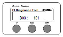
- "DIAG" appears on the LCD of the FI diagnostic tool.
- "POWER" LED (Green) comes on.
5. Press the "UP" button to select the CO adjustment mode "CO" or the diagnostic mode "DIAG".
6. After selecting "DIAG", press the "MODE" button.
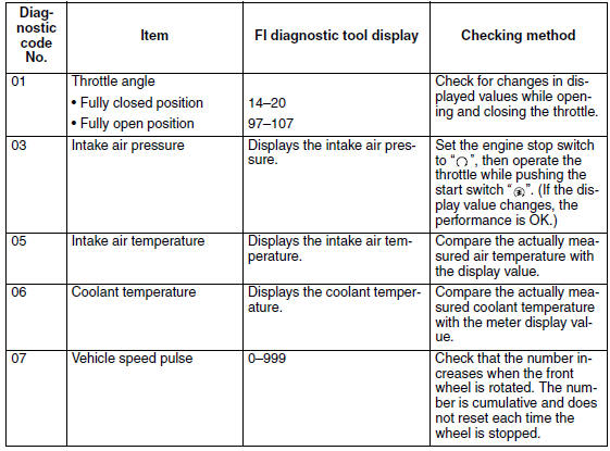
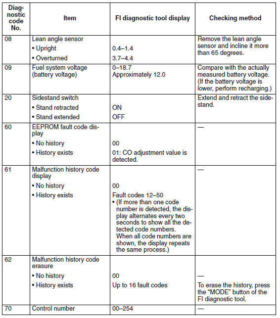
7. Select the diagnostic code number corresponding to the fault code number by pressing the "UP" and "DOWN" buttons.
NOTE:
- The diagnostic code number appears on the LCD (01-70).
- To decrease the selected diagnostic code number, press the "DOWN" button. Press the "DOWN" button for 1 second or longer to automatically decrease the diagnostic code numbers.
- To increase the selected diagnostic code number, press the "UP" button. Press the "UP" button for 1 second or longer to automatically increase the diagnostic code numbers.
8. Verify the operation of the sensor or actuator.
- Sensor operation The data representing the operating conditions of the sensor appear on the LCD.
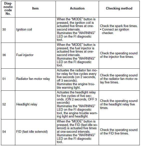
- Actuator operation
Press the "MODE" button.
9. Set the main switch to "OFF" to cancel the diagnostic mode.
10.Disconnect the FI diagnostic tool and connect the self-diagnosis signal connector.
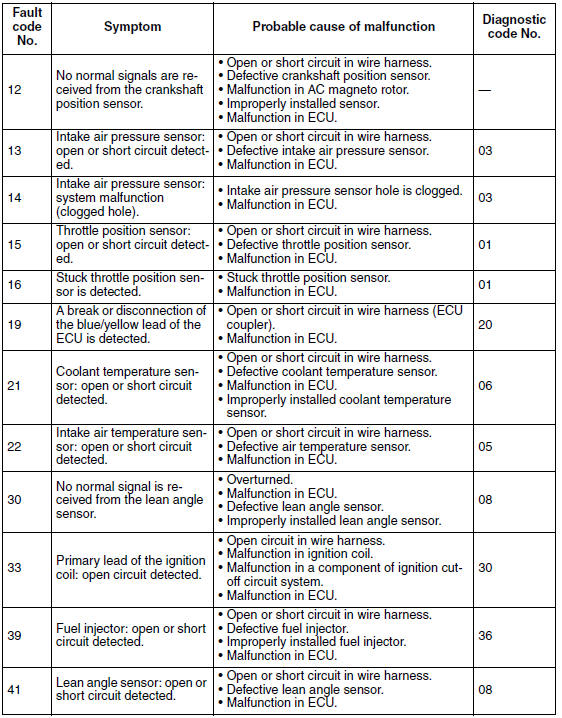
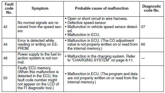
Diagnostic code table
Sensor operation table
Actuator operation table
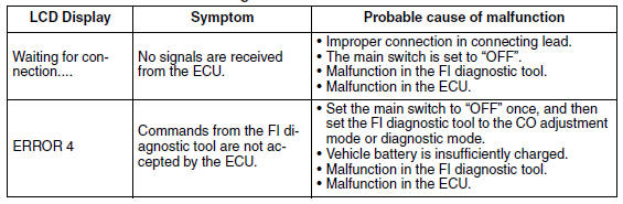
Communication error with the FI diagnostic tool
 Setting the normal mode
NOTE:
The engine speed, coolant temperature, and fault code, if detected, can be
displayed on the LCD of the
FI diagnostic tool when the tool is connected to the vehicle and is set to the
normal ...
 Troubleshooting details
This section describes the measures per fault code number displayed on the FI
diagnostic tool. Check
and service the items or components that are the probable cause of the
malfunction following t ...
Other materials:
Checking the cooling system
1. Remove:
Side covers
Upper side cowlings
Refer to "GENERAL CHASSIS" on page 4-1.
2. Check:
Radiator "1"
Radiator inlet hose "2"
Radiator outlet hose "3"
Coolant reservoir hose "4"
Water pump breather hose "5"
Cracks/damage → Replace.
Refer to "RADIATOR" on page 6-1 ...
Checking the stator coil
1. Disconnect:
Stator coil coupler
(from the wire harness)
2. Check:
Stator coil resistance
Out of specification → Replace the
crankshaft
position sensor/stator assembly.
a. Connect the pocket tester ( ×
1) to the stator
coil coupler as shown.
b. Measure the sta ...
Adjusting the throttle cable free play
NOTE:
Prior to adjusting the throttle cable free play, the
engine idling speed should be adjusted.
1. Check:
Throttle cable free play "a"
Out of specification →Adjust.
2. Remove:
Right side panel
Refer to "GENERAL CHASSIS" on page 4-1.
3. Adjust:
Throttle cable f ...