Yamaha YZF-R125 Service Manual: Setting the normal mode
NOTE:
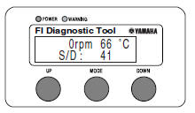
The engine speed, coolant temperature, and fault code, if detected, can be displayed on the LCD of the FI diagnostic tool when the tool is connected to the vehicle and is set to the normal mode.
1. Set the main switch to "OFF" and the engine stop switch to " ".
".
2. Disconnect the self-diagnosis signal connector "1", and then connect the FI diagnostic tool "2" as shown.
3. Set the main switch to "ON" and start the engine.
NOTE:
- The coolant temperature and engine speed appear on the LCD of the FI diagnostic tool.
- "POWER" LED (green) comes on.
- If a malfunction is detected in the system, the "WARNING" LED (orange) comes on.
4. Stop the engine.
NOTE:
If a malfunction is detected in the system, the fault code appears on the
LCD of the FI diagnostic tool
and the "WARNING" LED (orange) comes on.
5. Set the main switch to "OFF" to cancel the normal mode.
6. Disconnect the FI diagnostic tool and connect the self-diagnosis signal connector.
 Diagnostic mode
It is possible to monitor the sensor output data or check the activation of
actuators with the FI diagnostic
tool connected to the vehicle and set to the normal mode or the diagnostic
monitoring ...
 Setting the diagnostic mode
1. Set the main switch to "OFF" and the engine stop switch to "
".
2. Disconnect the self-diagnosis signal connector "1", and then connect the FI
diagnostic tool "2" as
shown.
3. Disconnect ...
Other materials:
Checking the bulbs and bulb sockets
NOTE:
Do not check any of the lights that use LEDs.
Check each bulb and bulb socket for damage or
wear, proper connections, and also for continuity
between the terminals.
Damage/wear Repair or replace
the bulb,
bulb socket or both.
Improperly connected Properly
connect.
No c ...
Installing the clutch
1. Install:
Conical spring washer "1"
NOTE:
Install the conical spring washer as shown in the
illustration.
2. Install:
Clutch housing
Thrust washer "1"
NOTE:
Be sure to install the thrust washer so that its
sharp edge "a" is facing away from the clutch
boss.
3. Instal ...
Multi-function display
Multi-function display
Multi-function display
"RESET/SELECT" button
WARNING
Be sure to stop the vehicle before
making any setting changes to the
multi-function display. Changing
settings while riding can distract the
operator and increase the risk of an
accident.
The multi- ...