Yamaha YZF-R125 Service Manual: Adjusting the valve clearance
The following procedure applies to all of the valves.
NOTE:
- Valve clearance adjustment should be made on a cold engine, at room temperature.
- When the valve clearance is to be measured or adjusted, the piston must be at top dead center (TDC) on the compression stroke.
1. Remove:
- Bottom cowling Refer to "GENERAL CHASSIS" on page 4-1.
- Fuel tank Refer to "FUEL TANK" on page 7-1.
2. Disconnect:
- Spark plug cap
3. Remove:
- Spark plug
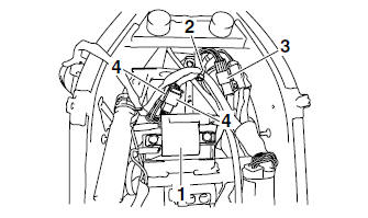
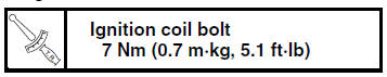
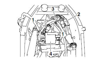
- Ignition coil "1"
- Plastic locking tie "2"
4. Disconnect:
- Main switch coupler "3"
- Left handlebar switch couplers "4"
- Cylinder head cover
- Cylinder head cover gasket Refer to "CYLINDER HEAD" on page 5-7.
NOTE:
When removing the cylinder head cover, lift it out from between the frame tubes.
5. Remove:
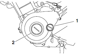
- Timing mark accessing screw "1"
- Crankshaft end accessing screw "2"
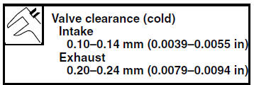
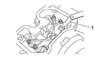
6. Measure:
- Valve clearance
Out of specification → Adjust.
a. Turn the crankshaft counterclockwise.
b. Align the TDC mark "a" on the generator rotor with the stationary pointer "b" on the generator cover.
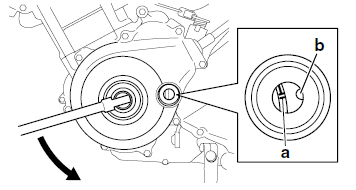
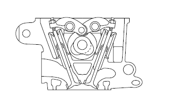
c. Check that the cam lobes are positioned as shown in the illustration.
d. Measure the valve clearance with a thickness gauge "1".
Out of specification → Adjust.
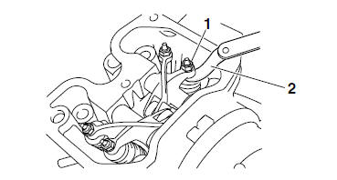
7. Adjust: - Valve clearance
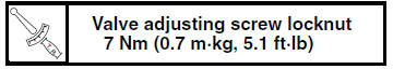
a. Loosen the locknut "1".
b. Insert a thickness gauge "2" between the end of the adjusting screw and the valve tip.
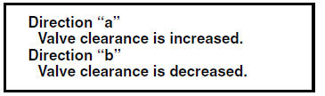
c. Turn the adjusting screw "3" in direction "a" or "b" until the specified valve clearance is obtained.
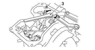
- Hold the adjusting screw to prevent it from
moving and tighten the locknut to specification.
d. Measure the valve clearance again.
e. If the valve clearance is still out of specification, repeat all of the valve clearance adjustment steps until the specified clearance is obtained.
8. Install:
- Crankshaft end accessing screw (along with the O-ring
 )
) - Timing mark accessing screw
(along with the O-ring
 )
)
9. Install:
- Cylinder head cover gasket

- Cylinder head cover
- Spark plug Refer to "CYLINDER HEAD" on page 5-7.
10.Connect:
- Left handlebar switch couplers "1"
- Main switch coupler "2"
11.Install:
- Plastic locking tie "3"

NOTE:
Fasten the wire harness (to horn), wire harness (to left handlebar switch), front brake light switch lead, right handlebar switch lead, and main switch lead to the frame with a plastic locking tie.
Refer to "CABLE ROUTING" on page 2-33.
12.Install:
- Ignition coil "4"
- Spark plug
13.Connect:
- Spark plug cap
14.Install:
- Fuel tank Refer to "FUEL TANK" on page 7-1.
- Bottom cowling Refer to "GENERAL CHASSIS" on page 4-1.
 Engine
...
 Adjusting the exhaust gas volume
NOTE:
Be sure to set the CO density level to standard,
and then adjust the exhaust gas volume.
1. Remove:
Rider seat
Refer to "GENERAL CHASSIS" on page 4-1.
2. Set the main switch to "OFF" ...
Other materials:
Checking the brake fluid level
1. Stand the vehicle on a level surface.
NOTE:
Place the vehicle on a suitable stand.
Make sure the vehicle is upright.
2. Check:
Brake fluid level
Below the minimum level mark "a" → Add the
recommended brake fluid to the proper level.
A. Front brake
B. Rear brake
WA ...
Preparation for removal and disassembly
1. Before removal and disassembly, remove all
dirt, mud, dust and foreign material.
2. Use only the proper tools and cleaning equipment.
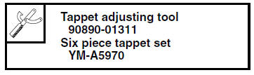
Refer to "SPECIAL TOOLS" on page 1-8.
3. When disassembling, always keep mated
parts together. This includes gears, cylinders,
pistons and other part ...
Checking the stator coil
1. Disconnect:
Stator coil coupler
(from the wire harness)
2. Check:
Stator coil resistance
Out of specification → Replace the
crankshaft
position sensor/stator assembly.
a. Connect the pocket tester ( ×
1) to the stator
coil coupler as shown.
b. Measure the sta ...