Yamaha YZF-R125 Service Manual: Assembling the oil pump
1. Lubricate:
- Oil pump inner rotor
- Oil pump outer rotor
- Oil pump driven gear
(with the recommended lubricant)
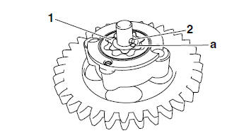
2. Install:
- Oil pump outer rotor
- Oil pump inner rotor "1"
- Oil pump driven gear
- Pin "2"
NOTE:
When installing the inner rotor, align the pin "2" in the oil pump shaft with the groove "a" in the inner rotor "1".
3. Check:
- Oil pump operation Refer to "CHECKING THE OIL PUMP" on page 5-49.
 Checking the oil pump
1. Check:
Oil pump drive gear
Oil pump driven gear
Oil pump housing
Oil pump housing cover
Cracks/damage/wear Replace the
defective
part(s).
2. Measure:
Inner-rotor-to-outer-r ...
 Installing the oil pump
1. Install:
Oil pump assembly
CAUTION:After tightening the screws, make sure
the
oil pump turns smoothly.
...
Other materials:
Catalytic converters
This vehicle is equipped with catalytic
converters in the exhaust system.
WARNING
The exhaust system is hot after operation.
To prevent a fire hazard or
burns:
Do not park the vehicle near
possible fire hazards such as
grass or other materials that
easily burn.
Park the vehic ...
Fuel tank cap
Fuel tank cap
Fuel tank cap lock cover
Unlock.
To remove the fuel tank cap
Open the fuel tank cap lock cover.
Insert the key into the lock and turn
it 1/4 turn counterclockwise. The
lock will be released and the fuel
tank cap can be removed.
To install the fuel tank ca ...
Checking the clutch housing
1. Check:
Clutch housing dogs "1"
Damage/pitting/wear
Deburr the clutch
housing dogs or replace the clutch housing.
NOTE:
Pitting on the clutch housing dogs will cause erratic
clutch operation.
2. Check:
Bearing
Damage/wear Replace the
bearing and
clutch housin ...