Yamaha YZF-R125 Service Manual: Installing the front brake master cylinder
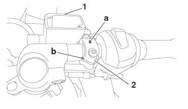
1. Install:
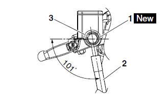
- Brake master cylinder "1"
- Brake master cylinder holder "2"
NOTE:
- Install the brake master cylinder holder with the arrow mark "a" pointing forward.
- Align the end of the brake master cylinder holder with the punch mark "b" on the handlebar.
- First, tighten the front bolt, then the rear bolt.
2. Install:
- Copper washers "1"

- Brake hose "2"
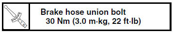
- Brake hose union bolt "3"
- Front brake light switch
| WARNING Proper brake hose routing is essential to insure safe vehicle operation. Refer to "CABLE ROUTING" on page 2-33. |
NOTE:
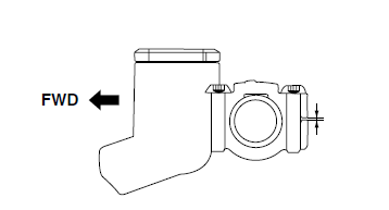
- Install the brake hose at an 101 angle to the front brake master cylinder as shown in the illustration.
- While holding the brake hose, tighten the brake hose union bolt as shown.
- Turn the handlebar to the left and right to make sure the brake hose does not touch other parts (e.g., wire harness, cables, leads). Correct if necessary.
3. Install:
- Front brake light switch
NOTE:
Before fully installing the front brake light switch, be sure to completely install the rubber cover over the switch. Also, be sure not to twist the front brake light switch lead when screwing in the switch.
4. Fill:
- Brake master cylinder reservoir
(with the specified amount of the recommended
brake fluid)
WARNING
|
| CAUTION: Brake fluid may damage painted surfaces and plastic parts. Therefore, always clean up any spilt brake fluid immediately. |
5. Bleed:
- Brake system Refer to "BLEEDING THE HYDRAULIC BRAKE SYSTEM" on page 3-20.
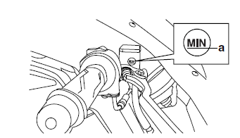
6. Check:
- Brake fluid level
Below the minimum level mark "a" →Add
the
recommended brake fluid to the proper level.
Refer to "CHECKING THE BRAKE FLUID LEVEL" on page 3-18.
7. Check:
Brake lever operation Soft or spongy feeling → Bleed the brake system.
Refer to "BLEEDING THE HYDRAULIC BRAKE SYSTEM" on page 3-20.
 Checking the front brake master cylinder
1. Check:
Brake master cylinder
Damage/scratches/wear Replace.
Brake fluid delivery passages
(brake master cylinder body)
Obstruction Blow out with
compressed air.
2. Check:
Br ...
 Rear brake
...
Other materials:
Owner's tool kit
Owner's tool kit
Owner's tool kit
Engine oil drain attachment
The owner's tool kit is located under the
rider seat.
The service information included in this
manual and the tools provided in the
owner's tool kit are intended to assist
you in the performance of preventive
maint ...
Checking the coolant temperature sensor
1. Remove:
Coolant temperature sensor
WARNING
Handle the coolant temperature sensor
with special care.
Never subject the coolant temperature sensor
to strong shocks. If the coolant temperature
sensor is dropped, replace it.
2. Check:
Coolant temper ...
Removing the rear brake master cylinder
NOTE:
Before removing the rear brake master cylinder,
drain the brake fluid from the entire brake system.
1. Disconnect:
Rear brake light switch coupler
2. Loosen:
Rear brake light switch "1"
3. Remove:
Rear brake master cylinder bolts
Rear brake master cylinder
4. Remove:
...