Yamaha YZF-R125 Service Manual: Circuit diagram
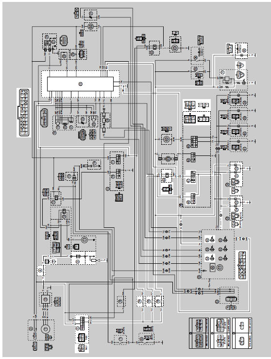
4. Main fuse
5. Main switch
9. Battery
25.ECU (engine control unit)
36.License plate light
37.Tail/brake light
44.Headlight relay
46.Pass switch
47.Dimmer switch
51.Headlight (low beam)
52.Auxiliary light
54.Headlight (high beam)
58.Meter light
60.High beam indicator light
64.Ignition fuse
65.Headlight fuse
66.Signaling system fuse
 Lighting system
...
 Troubleshooting
Any of the following fail to light: headlight, high beam indicator light,
taillight, license plate light, auxiliary
light or meter light.
NOTE:
Before troubleshooting, remove the following par ...
Other materials:
Handlebar switches
Left
Left
1. Pass switch "PASS"
2. Dimmer switch "/"
3. Turn signal switch "/"
4. Horn switch""
Right
Right
Engine stop switch "/"
Start switch""
Pass switch "PASS"
Press this switch to flash the headlight.
Dimmer switch "/"
Set this switch to""
for the high
beam an ...
Installing the exhaust assembly
1. Install:
Exhaust assembly "1"
Exhaust pipe nuts "2"
Exhaust assembly bolts "3" "4"
NOTE:
Do not fully tighten the nuts and bolts.
2. Tighten:
Exhaust pipe nuts "2"
Exhaust assembly bolt "4"
Exhaust assembly bolt "3"
...
Replacing the headlight bulbs
The following procedure applies to the low beam
headlight bulb.
1. Remove:
Headlight bulb cover "1"
2. Remove:
Headlight bulb holder "1"
3. Remove:
Headlight bulb "1"
WARNINGSince the headlight bulb gets extremely
hot,
keep flammable products and your ...