Yamaha YZF-R125 Owners Manual: Adjusting the clutch lever free play
Adjusting the clutch lever free play
- Clutch lever free play adjusting bolt
- Clutch lever free play
The clutch lever free play should measure 10.0-15.0 mm (0.39-0.59 in) as shown. Periodically check the clutch lever free play and, if necessary, adjust it as follows.
- Slide the rubber cover back at the clutch lever.
- Loosen the locknut.
- To increase the clutch lever free play, turn the adjusting bolt in direction (a). To decrease the clutch lever free play, turn the adjusting bolt in direction (b).
TIP
If the specified clutch lever free play
could be obtained as described above,
skip steps 4-7.
- Fully turn the adjusting bolt at the clutch lever in direction (a) to loosen the clutch cable.
- Loosen the locknut at the crankcase.
-
Locknut
-
Clutch lever free play adjusting nut (crankcase)
- To increase the clutch lever free play, turn the adjusting nut in direction (a). To decrease the clutch lever free play, turn the adjusting nut in direction (b).
- Tighten the locknut at the crankcase.
- Tighten the locknut at the clutch lever and then slide the rubber cover to its original position.
 Cast wheels
To maximize the performance, durability,
and safe operation of your vehicle,
note the following points regarding the
specified wheels.
The wheel rims should be checked
for cracks, bends o ...
 Checking the front brake lever free play
Checking the front brake lever free play
Brake lever free play
The brake lever free play should measure
2.0-5.0 mm (0.08-0.20 in) as
shown. Periodically check the brake lever
free pla ...
Other materials:
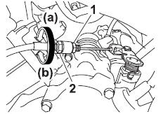
Removing the crankshaft
1. Remove:
Crankshaft "1"
NOTE:
Remove the crankshaft with the crankcase
separating tool "2".
Make sure the crankcase separating tool is
centered over the crankshaft.
CAUTION:
To protect the end of the crankshaft, place
an appropriate sized socket between the
c ...
Assembling the rear brake caliper
WARNING
Before installation, all internal brake components
should be cleaned and lubricated
with clean or new brake fluid.
Never use solvents on internal brake components
as they will cause the brake caliper
piston dust seal and piston seal to swell
and distort.
...
Checking the brake fluid level
Front brake
Front brake
Minimum level mark
Rear brake
Rear brake
Minimum level mark
Insufficient brake fluid may allow air to
enter the brake system, possibly causing
it to become ineffective.
Before riding, check that the brake fluid
is above the minimum level mark an ...