Yamaha YZF-R125 Service Manual: Checking the valve seats
The following procedure applies to all of the valves and valve seats.
1. Eliminate:
- Carbon deposits (from the valve face and valve seat)
2. Check:
- Valve seat
Pitting/wear
 Replace the
cylinder head.
3. Measure:
- Valve seat width C "a"
Out of specification
 Replace
the cylinder head.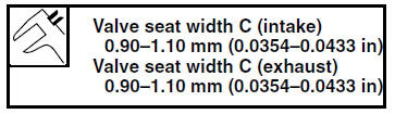
a. Apply Mechanic's blueing dye (Dykem) "b" onto the valve face.
b. Install the valve into the cylinder head.
c. Press the valve through the valve guide and onto the valve seat to make a clear impression.
d. Measure the valve seat width.
NOTE:
Where the valve seat and valve face contacted one another, the blueing will have been removed.
4. Lap:
- Valve face
- Valve seat
NOTE:
After replacing the cylinder head or replacing the valve and valve guide, the valve seat and valve face should be lapped.
a. Apply a coarse lapping compound "a" to the valve face.
| CAUTION: Do not let the lapping compound enter the gap between the valve stem and the valve guide. |
b. Apply molybdenum disulfide oil onto the valve stem.
c. Install the valve into the cylinder head.
d. Turn the valve until the valve face and valve seat are evenly polished, then clean off all of the lapping compound.
NOTE:
For the best lapping results, lightly tap the valve seat while rotating the valve back and forth between your hands.
e. Apply a fine lapping compound to the valve face and repeat the above steps.
f. After every lapping procedure, be sure to clean off all of the lapping compound from the valve face and valve seat.
g. Apply Mechanic's blueing dye (Dykem) "b" onto the valve face.
h. Install the valve into the cylinder head.
i. Press the valve through the valve guide and onto the valve seat to make a clear impression.
j. Measure the valve seat width "c" again. If the valve seat width is out of specification, reface and lap the valve seat.
 Checking the valves and valve guides
The following procedure applies to all of the
valves and valve guides.
1. Measure:
Valve-stem-to-valve-guide clearance
Out of specification Replace the
valve
guide.
Valve-stem-to-valve ...
 Checking the valve springs
The following procedure applies to all of the
valve springs.
1. Measure:
Valve spring free length "a"
Out of specification Replace the valve
spring.
2. Measure:
Compressed valve ...
Other materials:
Assembling the front brake caliper
WARNING
Before installation, all internal brake components
should be cleaned and lubricated
with clean or new brake fluid.
Never use solvents on internal brake components
as they will cause the brake caliper
dust seals and piston seals to swell and
distort.
...
Installing the throttle body
1. Install:
Throttle body joint clamps
NOTE:
Align the projections "a" on the throttle body joint
with the slot "b" in each throttle body joint clamp.
2. Install:
Throttle body joint
NOTE:
Align the projection "a" on the throttle body joint
with the slot "b" in the intake mani ...
Checking the spark plug cap
1. Check:
Spark plug cap resistance
Out of specification Replace.
a. Remove the spark plug cap from the spark
plug lead.
b. Connect the pocket tester ( × 1k)
to the
spark plug cap as shown.
c. Measure the spark plug cap resistance. ...