Yamaha YZF-R125 Service Manual: Checking the rocker arms and rocker arm shafts
The following procedure applies to all of the rocker arms and rocker arm shafts.
1. Check:
- Rocker arm
Damage/wear
 Replace.
2. Check:
- Rocker arm shaft
Blue discoloration/excessive wear/pitting/
scratches
 Replace or
check the lubrication system.
3. Measure:
- Rocker arm inside diameter "a"
Out of specification
 Replace.
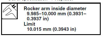
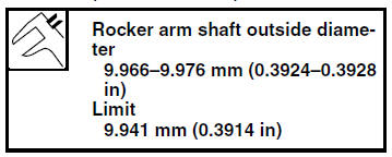
4. Measure:
- Rocker arm shaft outside diameter "a"
Out of specification Replace.
5. Calculate:
- Rocker-arm-to-rocker-arm-shaft clearance
NOTE:
Calculate the clearance by subtracting the rocker arm shaft outside diameter from the rocker arm inside diameter.
Out of specification  Replace the
defective
part(s).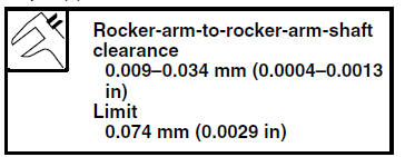
 Checking the camshaft
1. Check:
Camshaft lobes
Blue discoloration/pitting/scratches
Replace
the camshaft.
2. Measure:
Camshaft lobe dimensions "a" and "b"
Out of specification Replace
the cams ...
 Installing the camshaft and rocker arms
1. Lubricate:
Rocker arms
Rocker arm shafts
2. Lubricate:
Camshaft
3. Install:
Camshaft "1"
NOTE:
Make sure that the camshaft projections "a" and
hole "b" are positioned as s ...
Other materials:
Drive chain slack
The drive chain slack should be
checked before each ride and adjusted
if necessary.
To check the drive chain slack
Place the motorcycle on the sidestand.
TIP
When checking and adjusting the drive
chain slack, there should be no weight
on the motorcycle.
Shift the transmission in ...
Installing the thermostat
1. Install:
Thermostat
NOTE:
Install the thermostat with its breather hole "a"
facing up.
2. Install:
Copper washer
Coolant temperature sensor
CAUTION:Use extreme care when handling the
coolant
temperature sensor. Replace any part that
was dropped or subjected to ...
Checking the lean angle sensor
1. Remove:
Lean angle sensor
2. Check:
Lean angle sensor output voltage
Out of specification Replace.
a. Connect the lean angle sensor to the wire
harness.
b. Connect the pocket tester (DC 20 V) to the
lean angle sensor coupler as shown.
Positive tester probe
yellow/green "1"
Neg ...