Yamaha YZF-R125 Service Manual: Air induction system
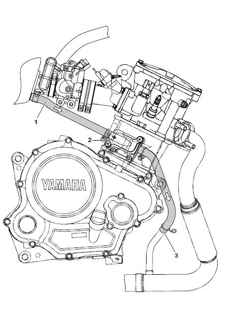
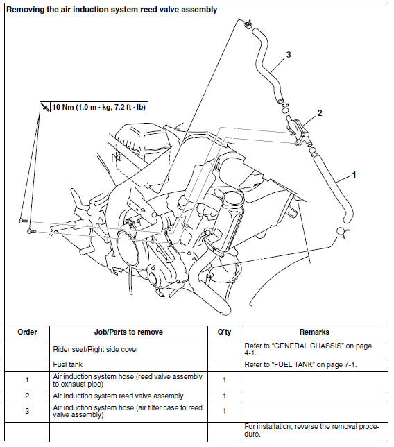
1. Air induction system hose (air filter case to reed valve assembly) 2. Air induction system reed valve assembly
3. Air induction system hose (reed valve assembly to exhaust pipe)
Checking the air induction system
Air injection
The air induction system burns unburned exhaust gases by injecting fresh air (secondary air) into the exhaust port, reducing the emission of hydrocarbons. When there is negative pressure at the exhaust port, the reed valve opens, allowing secondary air to flow into the exhaust port.
The required temperature for burning the unburned exhaust gases is approximately 600 to 700 C (1112 to 1292 F).
1. Check:
- Hoses
Loose connections
 Connect
properly.Cracks/damage
 Replace.
 - Cracks/damage
 Replace.
2. Check:
- Air induction system reed valve assembly operation
a. Blow air into the pipe "1" of the air induction system reed valve assembly and check that it comes out from the pipe "2".
b. Blow air into the pipe "2" of the air induction system reed valve assembly and check that it does not come out from the pipe "1".
c. If faulty, replace the air induction system reed valve assembly.
 Installing the throttle body
1. Install:
Throttle body joint clamps
NOTE:
Align the projections "a" on the throttle body joint
with the slot "b" in each throttle body joint clamp.
2. Install:
Throttle body joint ...

Other materials:
Troubleshooting
Any of the following fail to light: turn signal lights, brake light or
indicator lights.
The horn fails to sound.
The fuel gauge fails to operate.
The speedometer fails to operate.
NOTE:
Before troubleshooting, remove the following part(s):
1. Seats
2. Fuel tank
3. Left upper ...
Checking the front and rear brake pads
The front and rear brake pads must be
checked for wear at the intervals specified
in the periodic maintenance and
lubrication chart.
Front brake pads
Remove the front brake caliper by
removing the bolts.
Bolt
Brake caliper
Lining thickness
Check each front br ...
Checking the friction plates
The following procedure applies to all of the friction
plates.
1. Check:
Friction plate
Damage/wear Replace the
friction plates
as a set.
2. Measure:
Friction plate thickness
Out of specification Replace
the friction
plates as a set.
NOTE:
Measure the friction plate ...