Yamaha YZF-R125 Service Manual: Adjusting the engine idling speed
NOTE:
Prior to adjusting the engine idling speed, the air filter element should be clean, and the engine should have adequate compression.
1. Start the engine and let it warm up for several minutes.
2. Remove:
- Rider seat Refer to "GENERAL CHASSIS" on page 4-1.
3. Lift the fuel tank. (Do not disconnect the fuel hose, fuel drain hose, and couplers.) Refer to "FUEL TANK" on page 7-1.
4. Install:
- Digital tachometer (onto the spark plug lead)
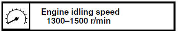
5. Check:
Engine idling speed
Out of specification → Adjust.
6. Remove:
- Right side panel Refer to "GENERAL CHASSIS" on page 4-1.
7. Adjust:
- Engine idling speed
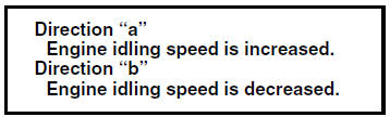
a. Turn the pilot screw "1" in direction "a" or "b" until the specified engine idling speed is obtained.
8. Remove:
- Digital tachometer
9. Install:
- Fuel tank Refer to "FUEL TANK" on page 7-1.
- Right side panel
- Rider seat Refer to "GENERAL CHASSIS" on page 4-1.
10.Adjust:
- Throttle cable free play
Refer to "ADJUSTING THE THROTTLE CABLE
FREE PLAY" on page 3-6.
 Adjusting the exhaust gas volume
NOTE:
Be sure to set the CO density level to standard,
and then adjust the exhaust gas volume.
1. Remove:
Rider seat
Refer to "GENERAL CHASSIS" on page 4-1.
2. Set the main switch to "OFF" ...
 Adjusting the throttle cable free play
NOTE:
Prior to adjusting the throttle cable free play, the
engine idling speed should be adjusted.
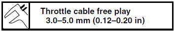
1. Check:
Throttle cable free play "a"
Out of specification →Adjust.
2. Remov ...
Other materials:
Checking the fuel sender
1. Drain the fuel from the fuel tank.
2. Check:
Fuel sender resistance
Out of specification → Replace the fuel
sender.
a. Connect the pocket tester ( ×
10) to the fuel
sender coupler as shown.
Positive tester probe
sky blue "1"
Negative tester probe
orange/white " ...
Removing the throttle body
1. Extract the fuel in the fuel tank through the
fuel tank filler hole with a pump.
2. Disconnect:
Fuel hose
WARNINGCover the fuel hose connections with a
cloth
when disconnecting them. Residual pressure
in the fuel lines could cause fuel to
spurt out when removing the h ...
Checking the front fork
1. Stand the vehicle on a level surface.
WARNINGSecurely support the vehicle so that there
is
no danger of it falling over.
2. Check:
Inner tube
Damage/scratches Replace.
Oil seal
Oil leakage Replace.
3. Hold the vehicle upright and apply the front
brake.
4. Che ...