Yamaha YZF-R125 Service Manual: Starting circuit cut-off system operation
If the engine stop switch is set to "
 " and the main switch is set to
"ON" (both switches are closed), the
starter motor can only operate if at least one of the following conditions is
met:
- The transmission is in neutral (the neutral switch is closed).
- The clutch lever is pulled to the handlebar (the clutch switch is closed) and the sidestand is up (the sidestand switch is closed).
The starting circuit cut-off relay prevents the starter motor from operating
when neither of these conditions
has been met. In this instance, the starting circuit cut-off relay is open so
current cannot reach the
starter motor. When at least one of the above conditions has been met, the
starting circuit cut-off relay
is closed and the engine can be started by pressing the start switch "
".
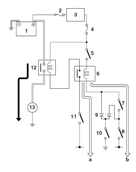
a. WHEN THE TRANSMISSION IS IN NEUTRAL
b. WHEN CLUTCH LEVER IS PULLED TO THE HANDLEBAR AND THE SIDESTAND IS UP
1. Battery
2. Main fuse
3. Main switch
4. Ignition fuse
5. Engine stop switch
6. Starting circuit cut-off relay
7. Clutch switch
8. Sidestand switch
9. Diode
10.Neutral switch
11.Start switch
12.Starter relay
13.Starter motor
 Circuit diagram
4. Main fuse
5. Main switch
7. Clutch switch
8. Sidestand switch
9. Battery
10.Starter relay
11.Starter motor
12.Starting circuit cut-off relay
13.Diode
14.Neutral switch
16.Start switch ...
 Troubleshooting
The starter motor fails to turn.
NOTE:
Before troubleshooting, remove the following part(s):
1. Seats
2. Fuel tank
3. Left lower side cowling
4. Left upper side cowling
...
Other materials:
Installing the drive chain
1. Lubricate:
Drive chain
Master link
2. Install:
Drive sprocket
Drive sprocket retainer bolts
3. Install:
Master link
O-rings
Master link plate
Master link clip "1"
CAUTION:
The closed end of the master link clip must
face in the direction of drive ch ...
Disassembling the front wheel
1. Remove:
Oil seal
Wheel bearings
a. Clean the surface of the front wheel hub.
b. Remove the oil seal "1" with a flat-head
screwdriver.
NOTE:
To prevent damaging the wheel, place a rag "2"
between the screwdriver and the wheel surface.
c. Remove the wheel bearings "3" with a ge ...
Checking the brake fluid level
Front brake
Front brake
Minimum level mark
Rear brake
Rear brake
Minimum level mark
Insufficient brake fluid may allow air to
enter the brake system, possibly causing
it to become ineffective.
Before riding, check that the brake fluid
is above the minimum level mark an ...