Yamaha YZF-R125 Service Manual: Special tools
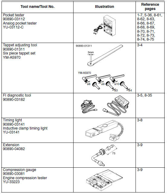
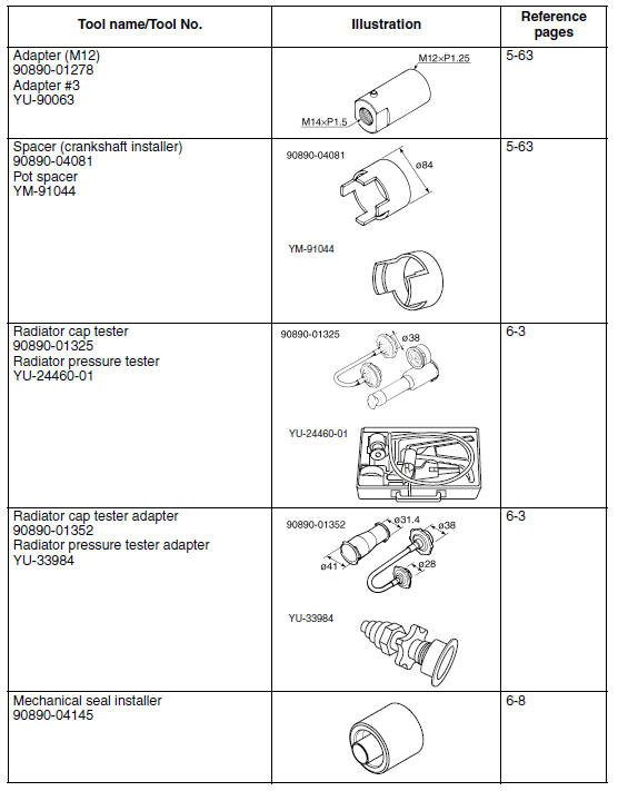
The following special tools are necessary for complete and accurate tune-up and assembly. Use only the appropriate special tools as this will help prevent damage caused by the use of inappropriate tools or improvised techniques. Special tools, part numbers or both may differ depending on the country.
When placing an order, refer to the list provided below to avoid any mistakes.
NOTE:
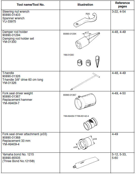
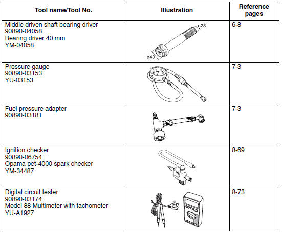
- For U.S.A. and Canada, use part number starting with "YM-", "YU-", or "ACC-".
- For others, use part number starting with "90890-".
 Checking the connections
Check the leads, couplers, and connectors for
stains, rust, moisture, etc.
1. Disconnect:
Lead
Coupler
Connector
2. Check:
Lead
Coupler
Connector
Moisture → Dry with an ...
 Specifications
General specifications
...
Other materials:
Periodic maintenance and lubrication chart
NOTE:
The annual checks must be performed every year, except if a
kilometer-based maintenance,
or for the UK, a mileage-based maintenance, is performed instead.
From 30000 km (17500 mi), repeat the maintenance intervals starting
from 6000 km (3500 mi).
Items marked with an asterisk s ...
Fuel tank cap
Fuel tank cap
Fuel tank cap lock cover
Unlock.
To remove the fuel tank cap
Open the fuel tank cap lock cover.
Insert the key into the lock and turn
it 1/4 turn counterclockwise. The
lock will be released and the fuel
tank cap can be removed.
To install the fuel tank ca ...
Disassembling the front wheel
1. Remove:
Oil seal
Wheel bearings
a. Clean the surface of the front wheel hub.
b. Remove the oil seal "1" with a flat-head
screwdriver.
NOTE:
To prevent damaging the wheel, place a rag "2"
between the screwdriver and the wheel surface.
c. Remove the wheel bearings "3" with a ge ...