Yamaha YZF-R125 Service Manual: Checking the fuses
The following procedure applies to all of the fuses.
| CAUTION: To avoid a short circuit, always turn the main switch to "OFF" when checking or replacing a fuse. |
1. Remove:
- Rider seat Refer to "GENERAL CHASSIS" on page 4-1.
2. Check:
- Fuse
a. Connect the pocket tester to the fuse and check the continuity.
Set the pocket tester selector to "
 × 1".
× 1".
b. If the pocket tester indicates " ", replace the fuse.
3. Replace:
- Blown fuse
a. Set the main switch to "OFF".
b. Install a new fuse of the correct amperage rating.
c. Set on the switches to verify if the electrical circuit is operational.
d. If the fuse immediately blows again, check
the electrical circuit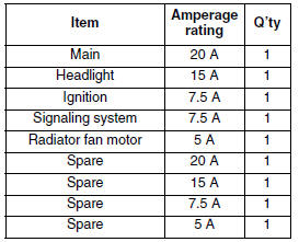
| WARNING Never use a fuse with an amperage rating other than that specified. Improvising or using a fuse with the wrong amperage rating may cause extensive damage to the electrical system, cause the lighting and ignition systems to malfunction and could possibly cause a fire. |
4. Install:
- Rider seat Refer to "GENERAL CHASSIS" on page 4-1.
 Checking the condition of the bulb sockets
The following procedure applies to all of the bulb
sockets.
1. Check:
Bulb socket (for continuity)
(with the pocket tester)
No continuity Replace.
NOTE:
Check each bulb socket for continui ...
 Checking and charging the battery
WARNINGBatteries generate explosive hydrogen gas
and contain electrolyte which is made of poisonous
and highly caustic sulfuric acid.
Therefore, always follow these preventive
mea ...
Other materials:
General tightening torque specifications
This chart specifies tightening torques for standard
fasteners with a standard ISO thread pitch.
Tightening torque specifications for special components
or assemblies are provided for each
chapter of this manual. To avoid warpage, tighten
multi-fastener assemblies in a crisscross pattern
and ...
Troubleshooting
Any of the following fail to light: headlight, high beam indicator light,
taillight, license plate light, auxiliary
light or meter light.
NOTE:
Before troubleshooting, remove the following part(s):
1. Seats
2. Fuel tank
...
Checking the ignition spark gap
1. Check:
Ignition spark gap
Out of specification Perform the
ignition
system troubleshooting, starting with step 5.
Refer to "TROUBLESHOOTING" on page
8-3.
NOTE:
If the ignition spark gap is within specification,
the ignition system circuit is operating normally.
a. Disconnect the spa ...