Yamaha YZF-R125 Service Manual: VInstalling the handlebars
1. Stand the vehicle on a level surface.
| WARNING Securely support the vehicle so that there is no danger of it falling over. |
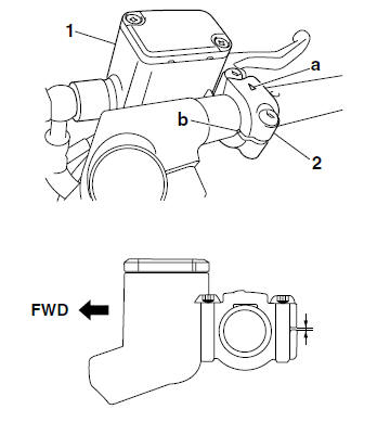
2. Install:
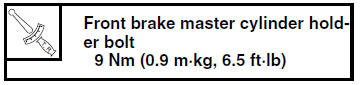
- Front brake master cylinder "1"
- Front brake master cylinder holder "2"
- Front brake light switch
NOTE:
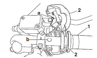
Install the brake master cylinder holder with the arrow mark "a" pointing forward.
- Align the mating surfaces of the brake master cylinder holder with the punch mark "b" on the handlebar.
- First, tighten the front bolt, then the rear bolt.
3. Install:
- Front brake light switch
NOTE:
Before fully installing the front brake light switch, be sure to completely install the rubber cover over the switch. Also, be sure not to twist the front brake light switch lead when screwing in the switch.
4. Install:
- Throttle grip "1"
- Throttle cable
- Right handlebar switch "2"
NOTE:
- Be sure to position the washer between the throttle grip and the right handlebar switch.
- Lubricate the end of the throttle cable and the inside of the throttle grip with a thin coat of the lithium-soap-based grease, and then install the throttle grip onto the right handlebar.
- Route the throttle cable through the slot in the throttle grip, and then install the cable.
- Align the projection "a" on the right handlebar switch with the hole "b" on the right handlebar.
5. Install:
- Right grip end "1"
NOTE:
There should be 1-3 mm (0.04-0.12 in) of clearance "a" between the throttle grip and the right grip end.
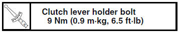
6. Install:
- Clutch lever holder "1"
NOTE:
Align the mating surfaces of the clutch lever holder with the punch mark "a" on the left handlebar.
7. Install:
- Clutch lever
- Clutch switch "1"
NOTE:
Align the projection "a" on the clutch switch with the slit "b" in the clutch lever holder.
8. Connect:
- Clutch cable
NOTE:
Lubricate the end of the clutch cable with a thin coat of lithium-soap-based grease.
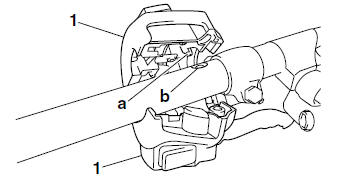
9. Install:
- Left handlebar switch "1"
NOTE:
Align the projection "a" on the left handlebar switch with the hole "b" in the left handlebar.
10.Connect:
- Clutch switch coupler
11.Install:
- Handlebar grip "1"
- Left grip end "2"
a. Apply a thin coat of rubber adhesive onto the end of the left handlebar.
b. Slide the handlebar grip over the end of the left handlebar.
c. Wipe off any excess rubber adhesive with a clean rag.
WARNING
Do not touch the handlebar grip until the rubber adhesive has fully dried.
NOTE:
There should be 3 mm (0.12 in) of clearance "a" between the handlebar grip and the grip end.
12.Check:
- Cable routing
NOTE:
Make sure the main switch lead, brake hose, throttle cable, clutch cable, and handlebar switch leads are routed properly. Refer to "CABLE ROUTING" on page 2-33.
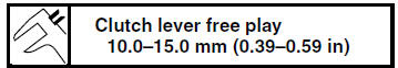
13.Adjust:
- Clutch lever free play
Refer to "ADJUSTING THE CLUTCH CABLE
FREE PLAY" on page 3-12.
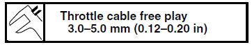
14.Adjust:
- Throttle cable free play
Refer to "ADJUSTING THE THROTTLE CABLE
FREE PLAY" on page 3-6.
 Checking the handlebars
1. Check:
Left handlebar
Right handlebar
Bends/cracks/damage → Replace.
WARNINGDo not attempt to straighten a bent
handlebar
as this may dangerously weaken it.
...
 Front fork
...
Other materials:
Cleaning and lubricating the drive chain
The drive chain must be cleaned and
lubricated at the intervals specified in
the periodic maintenance and lubrication
chart, otherwise it will quickly wear
out, especially when riding in dusty or
wet areas. Service the drive chain as
follows.
NOTICE
The drive chain must be lubricated
...
Checking the primary drive gear
1. Remove:
Primary drive gear
Refer to "BALANCER GEAR" on page 5-53.
2. Check:
Primary drive gear
Damage/wear Replace the
primary drive
gear and clutch housing as a set.
Excessive noise during operation
Replace
the primary drive gear and clutch housing as
a set
...
Faulty lighting or signaling system
Headlight does not come on
- Wrong headlight bulb
- Too many electrical accessories
- Hard charging
- Incorrect connection
- Improperly grounded circuit
- Poor contacts (main or light switch)
- Burnt-out headlight bulb
Headlight bulb burnt out
- Wrong headlight bulb
- Faulty battery
- Fau ...