
Yamaha YZF-R125 Owners Manual: Owner's tool kit
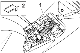
Owner's tool kit
- Owner's tool kit
- Engine oil drain attachment
The owner's tool kit is located under the rider seat.
The service information included in this manual and the tools provided in the owner's tool kit are intended to assist you in the performance of preventive maintenance and minor repairs. However, additional tools such as a torque wrench may be necessary to perform certain maintenance work correctly.
TIP
If you do not have the tools or experience
required for a particular job, have
a Yamaha dealer perform it for you.
TIP
- The annual checks must be performed every year, except if a kilometer-based maintenance, or for the UK, a mileage-based maintenance, is performed instead.
- From 30000 km (17500 mi), repeat the maintenance intervals starting from 6000 km (3500 mi).
- Items marked with an asterisk should be performed by a Yamaha dealer as they require special tools, data and technical skills.
 Periodic maintenance and adjustment
Periodic inspection, adjustment, and lubrication
will keep your vehicle in the
safest and most efficient condition possible.
Safety is an obligation of the vehicle
owner/operator. The most imp ...

Other materials:
Checking the shift drum assembly
1. Check:
Shift drum groove
Damage/scratches/wear Replace
the shift
drum assembly.
Shift drum segment "1"
Damage/wear Replace the
shift drum assembly.
Shift drum bearing "2"
Damage/pitting Replace the
shift drum assembly.
...
Changing the engine oil
1. Remove:
Right bottom cowling
Right upper side cowling
Right lower side cowling
Refer to "GENERAL CHASSIS" on page 4-1.
2. Start the engine, warm it up for several minutes,
and then turn it off.
3. Place a container under the engine oil drain
bolt.
4. Install:
Engine oil d ...
Setting the diagnostic mode
1. Set the main switch to "OFF" and the engine stop switch to "
".
2. Disconnect the self-diagnosis signal connector "1", and then connect the FI
diagnostic tool "2" as
shown.
3. Disconnect the fuel pump coupler.
4. While pressing the "MODE" button, set the main switch to "ON".
NOTE:
...