Yamaha YZF-R125 Service Manual: Assembling the oil pump
1. Lubricate:
- Oil pump inner rotor
- Oil pump outer rotor
- Oil pump driven gear
(with the recommended lubricant)
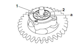
2. Install:
- Oil pump outer rotor
- Oil pump inner rotor "1"
- Oil pump driven gear
- Pin "2"
NOTE:
When installing the inner rotor, align the pin "2" in the oil pump shaft with the groove "a" in the inner rotor "1".
3. Check:
- Oil pump operation Refer to "CHECKING THE OIL PUMP" on page 5-49.
 Checking the oil pump
1. Check:
Oil pump drive gear
Oil pump driven gear
Oil pump housing
Oil pump housing cover
Cracks/damage/wear Replace the
defective
part(s).
2. Measure:
Inner-rotor-to-outer-r ...
 Installing the oil pump
1. Install:
Oil pump assembly
CAUTION:After tightening the screws, make sure
the
oil pump turns smoothly.
...
Other materials:
Installing the primary drive gear and balancer gears
1. Install:
Balancer driven gear "1"
Lock washer
Balancer drive gear "2"
Primary drive gear
Washer "3"
Balancer driven gear nut
Primary drive gear nut
NOTE:
Align the punch mark "a" in the balancer drive
gear "2" with the punch mark "b" in the balancer
driven gear "1".
...
Checking the lean angle sensor
1. Remove:
Lean angle sensor
2. Check:
Lean angle sensor output voltage
Out of specification Replace.
a. Connect the lean angle sensor to the wire
harness.
b. Connect the pocket tester (DC 20 V) to the
lean angle sensor coupler as shown.
Positive tester probe
yellow/green "1"
Neg ...
Setting the diagnostic mode
1. Set the main switch to "OFF" and the engine stop switch to "
".
2. Disconnect the self-diagnosis signal connector "1", and then connect the FI
diagnostic tool "2" as
shown.
3. Disconnect the fuel pump coupler.
4. While pressing the "MODE" button, set the main switch to "ON".
NOTE:
...