
Yamaha YZF-R125 Service Manual: Checking the lean angle sensor
1. Remove:
- Lean angle sensor
2. Check:
Lean angle sensor output voltage
Out of specification  Replace.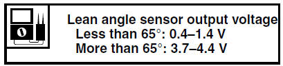
a. Connect the lean angle sensor to the wire harness.
b. Connect the pocket tester (DC 20 V) to the
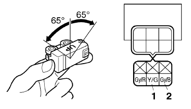
lean angle sensor coupler as shown.
Positive tester probe 
yellow/green "1"
Negative tester probe 
gray/black "2"
c. Set the main switch to "ON".
d. Tilt the lean angle sensor to 65.
e. Measure the lean angle sensor output voltage.
 Checking the crankshaft position sensor
1. Disconnect:
Crankshaft position sensor coupler
(from the wire harness)
2. Check:
Crankshaft position sensor resistance
Out of specification Replace
the crankshaft
position senso ...
 Checking the starter motor operation
1. Check:
Starter motor operation
Does not operate → Perform the electric
starting system troubleshooting, starting with
step 4.
Refer to "TROUBLESHOOTING" on page
8-9.
a. Con ...
Other materials:
Cleaning and lubricating the drive chain
The drive chain must be cleaned and
lubricated at the intervals specified in
the periodic maintenance and lubrication
chart, otherwise it will quickly wear
out, especially when riding in dusty or
wet areas. Service the drive chain as
follows.
NOTICE
The drive chain must be lubricated
...
Checking the drive chain
1. Measure:
15-link section "a" of the drive chain
Out of specification Replace the drive
chain.
a. Measure the length "a" between the inner
sides of the pins and the length "b" between
the outer sides of the pins on a 15-link section
of the drive chain as shown in the illustration.
...
Installing the rear shock absorber assembly
1. Install:
Rear shock absorber assembly
Relay arm "1"
NOTE:
Install the relay arm as shown in the illustration.
2. Tighten:
Rear shock absorber assembly upper nut
Relay arm nut
Rear shock absorber assembly lower nut
3. Install:
Connecting arms
NOTE:
When ins ...