Yamaha YZF-R125 Service Manual: Troubleshooting method
The engine operation is not normal and the engine trouble warning light comes on.
1. Check:
- Fault code number
a. Check the fault code number displayed on the FI diagnostic tool.
b. Identify the faulty system with the fault code.
Refer to "Self-Diagnostic Function table".
c. Identify the probable cause of the malfunction.
Refer to "Diagnostic code table".
2. Check and repair the probable cause of the
malfunction.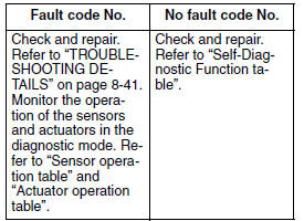
3. Perform fuel injection system reinstatement action.
Refer to "Reinstatement method" of table in "TROUBLESHOOTING DETAILS" on page 8-41.
4. Set the main switch to "OFF" and back to "ON", and then check that no fault code number is displayed.
NOTE:
If other fault codes are displayed, repeat steps (1) to (4) until no fault code number is displayed.
5. Erase the malfunction history in the diagnostic mode. Refer to "Sensor operation table (Diagnostic code No. 62)".
NOTE:
Setting the main switch to "OFF" will not erase the malfunction history.
The engine operation is not normal but the engine trouble warning light does not come on.
1. Check the operation of the following sensors
and actuators in the diagnostic mode. Refer
to "Sensor operation table" and "Actuator operation
table".
If a malfunction is detected in the sensors or actuators, repair or replace all faulty parts.
If no malfunction is detected in the sensors and actuators, check and repair the inner parts of the engine.
 Self-diagnostic function table
If the ECU detects an abnormal signal from a sensor while the vehicle is
being driven, the ECU illuminates
the engine trouble warning light and provides the engine with alternate
operating instru ...
 Diagnostic mode
It is possible to monitor the sensor output data or check the activation of
actuators with the FI diagnostic
tool connected to the vehicle and set to the normal mode or the diagnostic
monitoring ...
Other materials:
Operation and important riding points
Read the Owner's Manual carefully to
become familiar with all controls. If
there is a control or function you do not
understand, ask your Yamaha dealer.
WARNING
Failure to familiarize yourself with
the controls can lead to loss of control,
which could cause an accident
or injury.
TIP ...
Catalytic converters
This vehicle is equipped with catalytic
converters in the exhaust system.
WARNING
The exhaust system is hot after operation.
To prevent a fire hazard or
burns:
Do not park the vehicle near
possible fire hazards such as
grass or other materials that
easily burn.
Park the vehic ...