Yamaha YZF-R125 Service Manual: Separating the crankcase
1. Remove:
- Crankcase bolts
NOTE:
Loosen each bolt 1/4 of a turn at a time, in stages and in the proper sequence as shown.
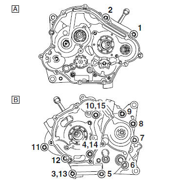
A. Right crankcase
B. Left crankcase
2. Turn:
- Shift drum segment
NOTE:
Turn the shift drum segment "1" to the position shown in the illustration. In this position, the shift drum segment teeth will not contact the crankcase during crankcase separation.
3. Remove:
- Right crankcase
| CAUTION: Tap on one side of the crankcase with a softface hammer. Tap only on reinforced portions of the crankcase, not on the crankcase mating surfaces. Work slowly and carefully and make sure the crankcase halves separate evenly. |
 Crankcase
...
 Checking the crankcase
1. Thoroughly wash the crankcase halves in a
mild solvent.
2. Thoroughly clean all the gasket surfaces and
crankcase mating surfaces.
3. Check:
Crankcase
Cracks/damage Replace.
Oil de ...
Other materials:
Checking the fuel sender
1. Drain the fuel from the fuel tank.
2. Check:
Fuel sender resistance
Out of specification → Replace the fuel
sender.
a. Connect the pocket tester ( ×
10) to the fuel
sender coupler as shown.
Positive tester probe
sky blue "1"
Negative tester probe
orange/white " ...
Checking the cylinder and piston
1. Check:
Piston wall
Cylinder wall
Vertical scratches Replace the
cylinder,
and replace the piston and piston rings as a
set.
2. Measure:
Piston-to-cylinder clearance
a. Measure cylinder bore "C" with the cylinder
bore gauge.
NOTE:
Measure cylinder bore "C" by takin ...
Removing the valves
The following procedure applies to all of the
valves and related components.
NOTE:
Before removing the internal parts of the cylinder
head (e.g., valves, valve springs, valve seats),
make sure the valves properly seal.
1. Check:
Valve sealing
Leakage at the valve seat Check
the valve
...