Yamaha YZF-R125 Service Manual: Replacing the front brake pads
NOTE:
When replacing the brake pads, it is not necessary to disconnect the brake hose or disassemble the brake caliper.
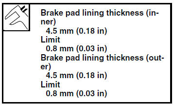
1. Measure:
- Brake pad wear limit "a"
Out of specification
 Replace
the brake pads as a set.
2. Install:
- Brake pad support

- Brake pad spring

- Brake pads

NOTE:
Always install new brake pads, a new brake pad spring and a new brake pad support as a set.
a. Connect a clear plastic hose "1" tightly to the bleed screw "2". Put the other end of the hose into an open container.
b. Loosen the bleed screw and push the brake caliper pistons into the brake caliper with your fingers.
c. Tighten the bleed screw. 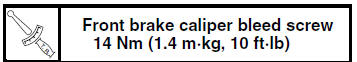
d. Install new brake pad support, a new brake pad spring and new brake pads.
NOTE:
The arrow mark "a" on the brake pad spring must point in the direction of disc rotation.
3. Install:
- Brake pad pin
- Brake pad clips
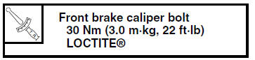
- Front brake caliper
4. Check:
- Brake fluid level
Below the minimum level mark "a" → Add
the
recommended brake fluid to the proper level.
Refer to "CHECKING THE BRAKE FLUID LEVEL" on page 3-18.
5. Check:
- Brake lever operation
Soft or spongy feeling
 Bleed
Bleed
the brake system.Refer to "BLEEDING THE HYDRAULIC BRAKE SYSTEM" on page 3-20.
 Checking the front brake disc
1. Remove:
Front wheel
Refer to "FRONT WHEEL" on page 4-6.
2. Check:
Brake disc
Damage/galling Replace.
3. Measure:
Brake disc deflection
Out of specification Correct the
b ...
 Removing the front brake caliper
NOTE:
Before disassembling the brake caliper, drain
the brake fluid from the entire brake system.
1. Remove:
Brake hose union bolt "1"
Copper washers "2"
Brake hose "3"
NOTE:
Put the en ...
Other materials:
Circuit diagram
4. Main fuse
5. Main switch
9. Battery
25.ECU (engine control unit)
36.License plate light
37.Tail/brake light
44.Headlight relay
46.Pass switch
47.Dimmer switch
51.Headlight (low beam)
52.Auxiliary light
54.Headlight (high beam)
58.Meter light
60.High beam indicator light
64.Ignit ...
Checking the front and rear brake pads
The front and rear brake pads must be
checked for wear at the intervals specified
in the periodic maintenance and
lubrication chart.
Front brake pads
Remove the front brake caliper by
removing the bolts.
Bolt
Brake caliper
Lining thickness
Check each front br ...
Checking and adjusting the steering head
1. Stand the vehicle on a level surface
WARNINGSecurely support the vehicle so that there
is
no danger of it falling over.
NOTE:
Place the vehicle on a suitable stand so that the
front wheel is elevated.
2. Check:
Steering head
Grasp the bottom of the front fork legs an ...