Yamaha YZF-R125 Service Manual: Measuring the compression pressure
NOTE:
Insufficient compression pressure will result in a loss of performance.
1. Measure:
Valve clearance Out of specification →Adjust.
Refer to "ADJUSTING THE VALVE CLEARANCE" on page 3-3.
2. Start the engine, warm it up for several minutes, and then turn it off.
3. Remove:
- Rider seat
- Right upper side cowling Refer to "GENERAL CHASSIS" on page 4-1.
4. Remove:
- Fuel tank Refer to "FUEL TANK" on page 7-1.
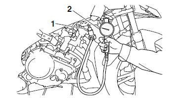
5. Disconnect:
- Coolant temperature sensor coupler "1"
- Spark plug cap "2"
6. Remove:
- Spark plug
| CAUTION: Before removing the spark plug, use compressed air to blow away any dirt accumulated in the spark plug well to prevent it from falling into the cylinder. |
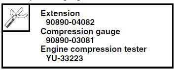
7. Install:
- Extension "1"
- Compression gauge "2"
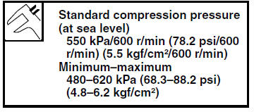
8. Measure:
- Compression pressure
Out of specification Refer to steps (c) and
(d).
a. Set the main switch to "ON".
b. With the throttle wide open, crank the engine until the reading on the compression gauge stabilizes.
c. If the compression pressure is above the maximum specification, check the cylinder head, valve surfaces and piston crown for carbon deposits.
Carbon deposits Eliminate.
d. If the compression pressure is below the minimum specification, pour a teaspoonful of engine oil into the spark plug bore and measure again.
Refer to the following table.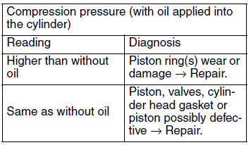
9. Remove:
- Extension
- Compression gauge
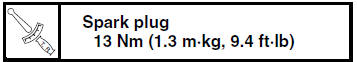
10.Install:
- Spark plug
11.Connect:
- Spark plug cap
- Coolant temperature sensor coupler
12.Install:
- Fuel tank Refer to "FUEL TANK" on page 7-1.
13.Install:
- Right upper side cowling
- Rider seat Refer to "GENERAL CHASSIS" on page 4-1.
 Checking the ignition timing
NOTE:
Prior to checking the ignition timing, check the
wiring connections of the entire ignition system.
Make sure all connections are tight and free of
corrosion.
1. Remove:
Rider seat
L ...
 Checking the engine oil level
1. Stand the vehicle on a level surface.
NOTE:
Place the vehicle on a suitable stand.
Make sure the vehicle is upright.
2. Start the engine, warm it up for several minutes,
and then turn it ...
Other materials:
Intake air temperature sensor
1. Check:
Intake air temperature sensor resistance
Out of specification Replace
the throttle
body.
a. Connect the pocket tester ( ×
1k) to the
throttle body sensor assembly coupler as
shown.
Positive tester probe
brown/white "1"
Negative tester probe
gray/black ...
Catalytic converters
This vehicle is equipped with catalytic
converters in the exhaust system.
WARNING
The exhaust system is hot after operation.
To prevent a fire hazard or
burns:
Do not park the vehicle near
possible fire hazards such as
grass or other materials that
easily burn.
Park the vehic ...
Checking the tires
The following procedure applies to both of the
tires.
1. Check:
Tire pressure
Out of specification Regulate.
WARNING
The tire pressure should only be checked
and regulated when the tire temperature
equals the ambient air temperature.
The tire pressure must be adjuste ...