Yamaha YZF-R125 Service Manual: Installing the swingarm
1. Lubricate:
- Bearings
- Spacers
- Dust covers
- Pivot shaft
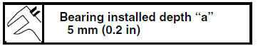
2. Install:
- Bearings "1"
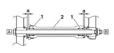
2. Swingarm
A. Left side
B. Right side
3. Install:
- Swingarm adjusting collar "1"
- Swingarm "2"
- Pivot shaft
- Pivot shaft nut "3"
a. Install, and then fully turn in the swingarm adjusting collar so that it contacts the frame.
b. Install the swingarm, pivot shaft, washer and pivot shaft nut.
NOTE:
Temporarily tighten the pivot shaft nut.
c. Turn the swingarm adjusting collar out to tighten it and so that it contacts the dust cover on the swingarm.
d. Tighten the pivot shaft nut.
e. Check the swingarm side play.
Refer to "REMOVING THE SWINGARM" on page 4-61.
4. Install:
- Rear shock absorber assembly
- Relay arm
- Rear wheel Refer to "REAR SHOCK ABSORBER ASSEMBLY" on page 4-56 and "REAR WHEEL" on page 4-12.
5. Adjust:
- Drive chain slack
Refer to "ADJUSTING THE DRIVE CHAIN
SLACK" on page 3-21.
 Checking the swingarm
1. Check:
Swingarm
Bends/cracks/damage
Replace.
2. Check:
Pivot shaft
Roll the pivot shaft on a flat surface.
Bends Replace.
WARNINGDo not attempt to straighten ...
 Chain drive
Removing the drive chain
1. Stand the vehicle on a level surface.
WARNINGSecurely support the vehicle so that there
is
no danger of it falling over.
NOTE:
Place the vehicle on ...
Other materials:
Aftermarket Parts, Accessories, and Modifications
While you may find aftermarket products
similar in design and quality to
genuine Yamaha accessories, recognize
that some aftermarket accessories
or modifications are not suitable because
of potential safety hazards to you
or others. Installing aftermarket products
or having other modif ...
Checking the switches
1. Clutch switch
2. Main switch
3. Front brake light switch
4. Sidestand switch
5. Rear brake light switch
6. Neutral switch
7. Turn signal switch
8. Horn switch
9. Dimmer switch
10.Pass switch
11.Engine stop switch
12.Start switch
Check each switch for continuity with the pocket tes ...
Cable routing
Front brake light switch lead
Right handlebar switch lead
Throttle cable
Main switch
Clutch cable
Clutch switch lead
Left handlebar switch lead
Sub-wire harness
Horn
Speed sensor lead
Front brake hose
Main switch lead
Left headlight assembly lead
Right headlight asse ...