Yamaha YZF-R125 Service Manual: Installing the relay arm
1. Lubricate:
- Spacers
- Bearings
- Oil seals
- Bolts (unthreaded shaft portion only)
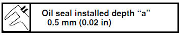
2. Install:
- Bearing "1" (to the relay arm)
- Oil seal "2"
(to the relay arm)
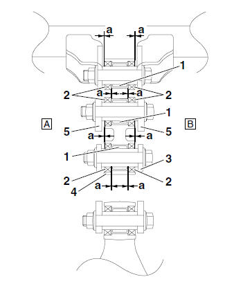
3. Rear shock absorber assembly
4. Relay arm
5. Connecting arm
A. Left side
B. Right side
 Checking the connecting arms and relay arm
1. Check:
Connecting arms
Relay arm
Damage/wear Replace.
2. Check:
Bearings
Oil seals
Damage/pitting Replace.
3. Check:
Spacers
Damage/scratches Replace.
...
 Installing the rear shock absorber assembly
1. Install:
Rear shock absorber assembly
Relay arm "1"
NOTE:
Install the relay arm as shown in the illustration.
2. Tighten:
Rear shock absorber assembly upper nut
Relay arm nu ...
Other materials:
Checking the swingarm
1. Check:
Swingarm
Bends/cracks/damage
Replace.
2. Check:
Pivot shaft
Roll the pivot shaft on a flat surface.
Bends Replace.
WARNINGDo not attempt to straighten a bent pivot
shaft.
3. Wash:
Pivot shaft
Washer
Swingarm adjusting collar
Du ...
Replacing the headlight bulbs
The following procedure applies to the low beam
headlight bulb.
1. Remove:
Headlight bulb cover "1"
2. Remove:
Headlight bulb holder "1"
3. Remove:
Headlight bulb "1"
WARNINGSince the headlight bulb gets extremely
hot,
keep flammable products and your ...
Fuel tank cap
Fuel tank cap
Fuel tank cap lock cover
Unlock.
To remove the fuel tank cap
Open the fuel tank cap lock cover.
Insert the key into the lock and turn
it 1/4 turn counterclockwise. The
lock will be released and the fuel
tank cap can be removed.
To install the fuel tank ca ...