Yamaha YZF-R125 Service Manual: Installing the rear shock absorber assembly
1. Install:
- Rear shock absorber assembly
- Relay arm "1"
NOTE:
Install the relay arm as shown in the illustration.
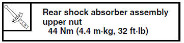
2. Tighten:
- Rear shock absorber assembly upper nut
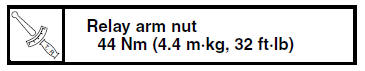
- Relay arm nut
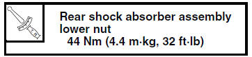
- Rear shock absorber assembly lower nut
3. Install:
- Connecting arms
NOTE:
When installing the connecting arms, lift up the swingarm.
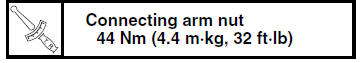
4. Tighten:
- Connecting arm nuts
 Installing the relay arm
1. Lubricate:
Spacers
Bearings
Oil seals
Bolts (unthreaded shaft portion only)
2. Install:
Bearing "1"
(to the relay arm)
Oil seal "2"
(to the relay arm)
3. Rear shoc ...
 Swingarm
...
Other materials:
Preparation for removal and disassembly
1. Before removal and disassembly, remove all
dirt, mud, dust and foreign material.
2. Use only the proper tools and cleaning equipment.
Refer to "SPECIAL TOOLS" on page 1-8.
3. When disassembling, always keep mated
parts together. This includes gears, cylinders,
pistons and other part ...
Checking the bulbs and bulb sockets
NOTE:
Do not check any of the lights that use LEDs.
Check each bulb and bulb socket for damage or
wear, proper connections, and also for continuity
between the terminals.
Damage/wear Repair or replace
the bulb,
bulb socket or both.
Improperly connected Properly
connect.
No c ...
Sidestand
The sidestand is located on the left side
of the frame. Raise the sidestand or
lower it with your foot while holding the
vehicle upright.
TIP
The built-in sidestand switch is part of
the ignition circuit cut-off system, which
cuts the ignition in certain situations.
WARNING
The vehicl ...