
Yamaha YZF-R125 Service Manual: Installing the engine
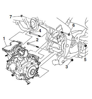
1. Install:
- Engine "1"
- Engine mounting bolt (rear lower side) "2"
- Engine mounting nut (rear lower side) "3"
- Engine mounting bolt (rear upper side) "4"
- Engine mounting nut (rear upper side) "5"
- Engine mounting bolt (front side) "6"
- Engine mounting nut (front side) "7"
NOTE:
Do not fully tighten the bolts and nuts.
2. Tighten:
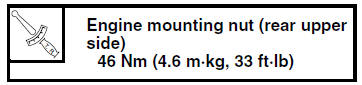
- Engine mounting nut (rear upper side)
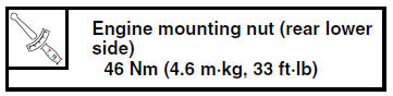
- Engine mounting nut (rear lower side)
- Engine mounting nut (front side)

 Engine removal
...
 Installing the shift arm
1. Install:
Shift arm "1"
NOTE:
Make sure that the distance "a" between the
center of the left rider footrest "2" and the center
of the shift pedal "3" is within specification.
...
Other materials:
Checking the cylinder head breather hose
1. Remove:
Left side panel
Refer to "GENERAL CHASSIS" on page 4-1.
2. Check:
Cylinder head breather hose "1"
Cracks/damage → Replace.
Loose connection → Connect properly.
CAUTION:Make sure the cylinder head
breather hose is
routed correctly.
...
Changing the engine oil
1. Remove:
Right bottom cowling
Right upper side cowling
Right lower side cowling
Refer to "GENERAL CHASSIS" on page 4-1.
2. Start the engine, warm it up for several minutes,
and then turn it off.
3. Place a container under the engine oil drain
bolt.
4. Install:
Engine oil d ...
Checking the piston pin
1. Check:
Piston pin
Blue discoloration/grooves
Replace the
piston pin and then check the lubrication system.
2. Measure:
Piston pin outside diameter "a"
Out of specification Replace
the piston pin.
3. Measure:
Piston pin bore diameter "b"
Out of specifica ...