Yamaha YZF-R125 Service Manual: Disassembling the front fork legs
The following procedure applies to both of the front fork legs.
1. Remove:
- Rubber cap
- Clip "1"
- Front fork cap "2" (with O-ring)
- Fork spring
NOTE:
Push the front fork cap in the direction of the arrow shown in the illustration to remove the clip.
2. Drain:
- Fork oil
NOTE:
Stroke the inner tube several times while draining the fork oil.
3. Remove:
- Dust seal "1"
- Oil seal clip "2" (with a flat-head screwdriver)
| CAUTION: Do not scratch the inner tube.
|
4. Remove:
- Damper rod bolt "1"
- Damper rod
NOTE:
While holding the damper rod with the damper
rod holder "2" and T-handle "3", loosen the
damper rod bolt. 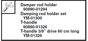
 Removing the front fork legs
The following procedure applies to both of the
front fork legs.
1. Stand the vehicle on a level surface.
WARNINGSecurely support the vehicle so that there
is
no danger of ...
 Checking the front fork legs
The following procedure applies to both of the
front fork legs.
1. Check:
Inner tube
Outer tube
Bends/damage/scratches
Replace.
WARNINGDo not attempt to straighten a bent inner ...
Other materials:
Multi-function display
1. Multi-function display
2. "RESET/SELECT" button
The multi-function display is equipped with the
following:
a speedometer (which shows the riding speed)
an odometer (which shows the total distance
traveled)
two tripmeters (which show the distance traveled
since they were last ...
Aftermarket Parts, Accessories, and Modifications
While you may find aftermarket products
similar in design and quality to
genuine Yamaha accessories, recognize
that some aftermarket accessories
or modifications are not suitable because
of potential safety hazards to you
or others. Installing aftermarket products
or having other modif ...
Ignition circuit cut-off system
The ignition circuit cut-off system (comprising
the sidestand switch, clutch
switch and neutral switch) has the following
functions.
It prevents starting when the transmission
is in gear and the sidestand
is up, but the clutch lever is
not pulled.
It prevents starting when the t ...