Yamaha YZF-R125 Service Manual: Circuit diagram
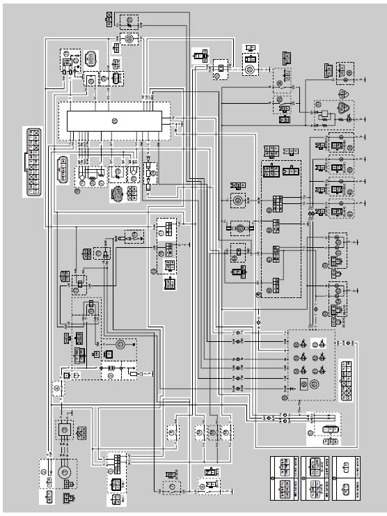
2. Crankshaft position sensor
4. Main fuse
5. Main switch
6. Radiator fan motor fuse
8. Sidestand switch
9. Battery
17.Engine stop switch
19.Intake air pressure sensor
20.Intake air temperature sensor
21.Throttle position sensor
22.Coolant temperature sensor
23.Lean angle sensor
24.Self-diagnosis signal connector
25.ECU (engine control unit)
26.Ignition coil
27.Spark plug
28.FID (fast idle solenoid)
29.Fuel injector
30.Fuel pump
32.Radiator fan motor relay
33.Radiator fan motor
63.Engine trouble warning light
64.Ignition fuse
66.Signaling system fuse
67.Speed sensor

 Ecu self-diagnostic function
The ECU is equipped with a self-diagnostic function in order to ensure that
the fuel injection system is
operating normally. If this function detects a malfunction in the system, it
immediately o ...
Other materials:
Installing the exhaust assembly
1. Install:
Exhaust assembly "1"
Exhaust pipe nuts "2"
Exhaust assembly bolts "3" "4"
NOTE:
Do not fully tighten the nuts and bolts.
2. Tighten:
Exhaust pipe nuts "2"
Exhaust assembly bolt "4"
Exhaust assembly bolt "3"
...
Adjusting the engine idling speed
The engine idling speed must be
checked and, if necessary, adjusted as
follows at the intervals specified in the
periodic maintenance and lubrication
chart.
The engine should be warm before
making this adjustment.
Remove panel A.
Check the engine idling speed
and, if necessary, ...
Ecu self-diagnostic function
The ECU is equipped with a self-diagnostic function in order to ensure that
the fuel injection system is
operating normally. If this function detects a malfunction in the system, it
immediately operates the engine
under substitute characteristics and illuminates the engine trouble warning
li ...