Yamaha YZF-R125 Service Manual: Circuit diagram
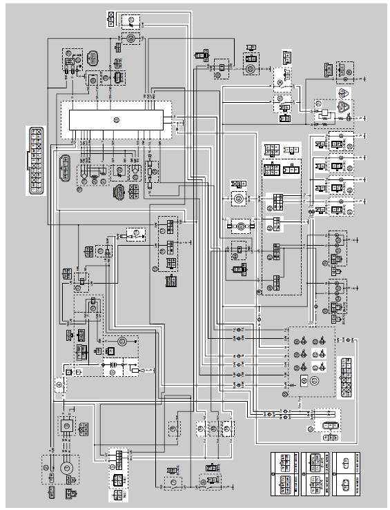
4. Main fuse
5. Main switch
9. Battery
14.Neutral switch
25.ECU (engine control unit)
31.Fuel sender
34.Rear brake light switch
35.Front brake light switch
37.Tail/brake light
38.Rear right turn signal light
39.Rear left turn signal light
40.Front right turn signal light
41.Front left turn signal light
42.Turn signal relay
43.Horn
48.Horn switch
49.Turn signal switch
56.Multi-function meter
57.Tachometer
61.Turn signal indicator light
62.Neutral indicator light
64.Ignition fuse
66.Signaling system fuse
67.Speed sensor
 Signaling system
...
 Troubleshooting
Any of the following fail to light: turn signal lights, brake light or
indicator lights.
The horn fails to sound.
The fuel gauge fails to operate.
The speedometer fails to operate.
NOTE ...
Other materials:
Checking the starter motor
1. Check:
Commutator
Dirt Clean with 600 grit
sandpaper.
2. Measure:
Commutator diameter "a"
Out of specification Replace
the starter
motor.
3. Measure:
Mica undercut "a"
Out of specification Scrape
the mica to the
proper measurement with a hacksaw blade
...
Checking the swingarm
1. Check:
Swingarm
Bends/cracks/damage
Replace.
2. Check:
Pivot shaft
Roll the pivot shaft on a flat surface.
Bends Replace.
WARNINGDo not attempt to straighten a bent pivot
shaft.
3. Wash:
Pivot shaft
Washer
Swingarm adjusting collar
Du ...
Checking the ignition coil
1. Check:
Primary coil resistance
Out of specification Replace.
a. Disconnect the ignition coil connectors from
the ignition coil terminals.
b. Connect the pocket tester ( × 1)
to the ignition
coil as shown.
Positive tester probe
red/white "1"
Negative tester probe
orange ...